Hello guys,
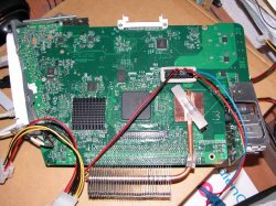
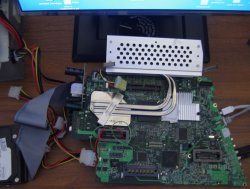
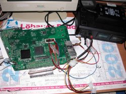
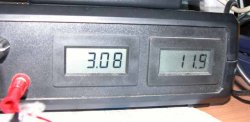
the Gen 3 board is running... just still with a b/w video on the internal, maybe it's just a missing wire or so... will look for it in the evening. The board takes at the 12 V line (without drives) 3.12 Ampere.
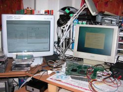
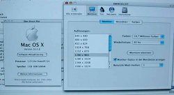
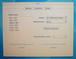
Now i'm installing X.3...
Not bad for 180 Euros.
So long.
MrFX
the Gen 3 board is running... just still with a b/w video on the internal, maybe it's just a missing wire or so... will look for it in the evening. The board takes at the 12 V line (without drives) 3.12 Ampere.
Now i'm installing X.3...
Not bad for 180 Euros.
So long.
MrFX