Become a MacRumors Supporter for $50/year with no ads, ability to filter front page stories, and private forums.

MacTech68

macrumors 68020
Mar 16, 2008
2,393
209
Australia, Perth
...when plug into the Q950, I get nothing. Voltages w/o the term is ~2mv, and with the term its a solid 4.71v.

Is that with the passive terminator (not the new active one you bought) ?

If 'yes' then I suspect the Termination Power from the motherboard is shot (if I'm determining things correctly). :eek:

If you have no termination power, and a terminator is on the SCSI BUS, you really will get a scrambled SCSI chain.

Did you try (in case SCSI Voodoo works) the smaller 68-50pin adapter, with the 50 pin cable and NO terminator ?

Otherwise ---

AFAIK, term power should be pretty precise, like 5.0x Volts.

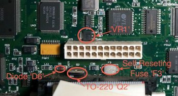
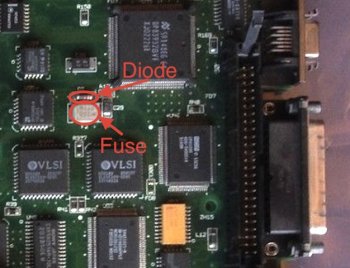
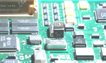
The fuse 'F3' should measure shorted. They can be difficult to get to one end to measure - you'll need a fine point on your multimeter probe. The top is one connection, the other is the non-rounded end (the end with the arrow head in the pic below). They're self-resetting fuses, but still can be worth checking. IIRC, the fuse and diode carry the 5volt termination power to pin 26.

Check the diode to make sure it has low resistance in one direction only. You could even check both sides of the diode (with reference to ground) to see if you get 5 volts on both sides. Again IIRC, you should.

I see on the 950 motherboard there is a TO-220 case next to the 50 Pin SCSI connector, between that and the motherboard power connector marked as Q2. There is also another surface mounted regulator marked VR1. (See pic)

Can you see what is written on Q2 and VR1? Do any of their pins connect to pin 26 on the 50 pin connector? Or, are they connected via the diode 'D6' ?

Sadly, I don't have a 950 or WGS95 here to check this out. :(
 

Attachments

  • Q950 SCSI Annot.jpg
    Q950 SCSI Annot.jpg
    246 KB · Views: 753

SirFoxx

macrumors regular
Original poster
Jul 9, 2012
137
2
Galien, Michigan
Is that with the passive terminator (not the new active one you bought) ?

Did you try (in case SCSI Voodoo works) the smaller 68-50pin adapter, with the 50 pin cable and NO terminator ?
I was only using a 50-pin cable with a passive terminator, along with a working 50-pin apple branded hard drive. If that won't show up, then the odds of the 68-pin showing up are pretty low IMO.
AFAIK, term power should be pretty precise, like 5.0x Volts.
I checked the voltage off of the power supply and it was 5.13v, so I don't think it is a PSU issue.
Check the diode to make sure it has low resistance in one direction only. You could even check both sides of the diode (with reference to ground) to see if you get 5 volts on both sides. Again IIRC, you should.
On the diode I get 105 ohm one way. The voltage on the diode with the 50-pin cable, passive terminator, and hard drive is .3v, and the fuse is only .02v. When checking the fuse with the ohm meter, I get 1 ohm.
Can you see what is written on Q2 and VR1? Do any of their pins connect to pin 26 on the 50 pin connector? Or, are they connected via the diode 'D6' ?
I cannot see what is written on Q2--the legs are soldered all the way to the bottom the part, making it impossible to bend far enough to see what is written on it. As for VR1 it is a 79M05--5v regulator.
 

MacTech68

macrumors 68020
Mar 16, 2008
2,393
209
Australia, Perth
I was only using a 50-pin cable with a passive terminator, along with a working 50-pin apple branded hard drive. If that won't show up, then the odds of the 68-pin showing up are pretty low IMO.
Agreed

I checked the voltage off of the power supply and it was 5.13v, so I don't think it is a PSU issue.
The Termination Power most likely has it's own voltage regulator on the motherboard.

On the diode I get 105 ohm one way. The voltage on the diode with the 50-pin cable, passive terminator, and hard drive is .3v, and the fuse is only .02v. When checking the fuse with the ohm meter, I get 1 ohm.
If the voltage ACROSS the diode is .3V then that's probably correct. If that's from one side of the diode to ground then that's NOT and your Term Power is missing.

I cannot see what is written on Q2--the legs are soldered all the way to the bottom the part, making it impossible to bend far enough to see what is written on it. As for VR1 it is a 79M05--5v regulator.

Yes, VR1 would be a negative 5V regulator. Check each pin to see if one of them is very close to negative 5 volts with respect to ground. I still wonder what Q2's purpose is. It's very close to the TERMPWR components and the SCSI Connector.

The alternative is to get a drive that supplies TERMPWR to the SCSI BUS (some do, some don't and some are configurable with jumpers) and place it along the internal SCSI chain.

EDIT - or, build your own TermPwr feeder.
 
Last edited:

SirFoxx

macrumors regular
Original poster
Jul 9, 2012
137
2
Galien, Michigan
Now if I were to build a feeder, would taking 5v from the power supply and connecting it to pin 26 work? Also is there anyway I can test this before I buy parts to make something?

edit: I also checked the diode again and I got 5.13v on both sides.
 

MacTech68

macrumors 68020
Mar 16, 2008
2,393
209
Australia, Perth
Now if I were to build a feeder, would taking 5v from the power supply and connecting it to pin 26 work? Also is there anyway I can test this before I buy parts to make something?

edit: I also checked the diode again and I got 5.13v on both sides.

Hmmm. I'd be tracing that diode to see if you can work out where is connects to. If you get 5.13v there, but it doesn't get to pin 26 on the 50pin connector, then somewhere there is the problem.

Does your multimeter have a 'continuity check' with a buzzer? That might help to trace it.

Check again that you're NOT seeing +5volt on pin 26, whilst confirming it is on both sides of the diode. Check both sides of the fuse (even though it seems the fuse is ok).

EDIT -

A feeder SHOULD consist of a fuse (1.5 Amp) and a shottky barrier diode at a minimum. The diode prevents backfeeding the 5V into the 5V supply from other devices on the SCSI BUS and the fuse prevents destroying the 5v power supply from over-current events.

If you build a feeder like this, it's still best to use the Active terminator, since it ties the data signals to an extremely accurate voltage.

You might get away with bridging a 5volt power from one of the Q950's 4 pin drive power connectors to pin 26 which would then supply power to the Active Terminator. At the VERY least a 1.5Amp fuse should be used on that connection - actually it's a MUST. So long as there are no other drives connected that might supply 5v power back onto the BUS via Term Power.

EDIT 2 -

as a side note, you'll find another diode and fuse for the second port performing the same function.
 

Attachments

  • Q950 SCSI Ext Annot.jpg
    Q950 SCSI Ext Annot.jpg
    94.8 KB · Views: 237
Last edited:

SirFoxx

macrumors regular
Original poster
Jul 9, 2012
137
2
Galien, Michigan
Hmmm. I'd be tracing that diode to see if you can work out where is connects to. If you get 5.13v there, but it doesn't get to pin 26 on the 50pin connector, then somewhere there is the problem.

Check again that you're NOT seeing +5volt on pin 26, whilst confirming it is on both sides of the diode. Check both sides of the fuse (even though it seems the fuse is ok).

I rechecked it, and I am getting 5.13 on one side of the diode and on the other side I am getting 4.8v, and the fuse has the same voltages. Is it possible that the diode is faulty, or is that normal for the diode to drop some voltage? And yes, pin 26 only has 4.7v on it. Should I check the voltage on one of my other macs to make sure it needs to be higher?

edit: I read a wiki article about termination. This is what it said about the voltages: "This positive voltage is called TERMPOWER and is usually around +4.3 volts. TERMPOWER is normally generated by a diode connection to +5.0 volts." I'll check the voltages on my g3 since I know my performa's PSU is dying, and I'm not sure on the on the other mac I have.
 
Last edited:

MacTech68

macrumors 68020
Mar 16, 2008
2,393
209
Australia, Perth
I rechecked it, and I am getting 5.13 on one side of the diode and on the other side I am getting 4.8v, and the fuse has the same voltages. Is it possible that the diode is faulty, or is that normal for the diode to drop some voltage? And yes, pin 26 only has 4.7v on it. Should I check the voltage on one of my other macs to make sure it needs to be higher?

Does the 4.7volt on pin 26 appear WITHOUT a terminator fitted ?
 

MacTech68

macrumors 68020
Mar 16, 2008
2,393
209
Australia, Perth
WITHOUT the terminator it is 4.89v on pin 26.
Ok, well, after all that, you ARE getting TermPower. The active terminator should be able to provide proper termination with that voltage. The regulator inside the active terminator outputs something around 2.85volts to a set of resistors, to tie the data signals to that 2.85volts.

A passive terminator ties each data signal to a resistor to ground AND a resistor to 5 volt - much LESS accurate.

If you re-check the drive NOW, without disturbing the motherboard (as much as possible), do you still have the 'SCSI ID 4 - check termination' error when the active terminator is connected to the end of the cable?
 

SirFoxx

macrumors regular
Original poster
Jul 9, 2012
137
2
Galien, Michigan
If you re-check the drive NOW, without disturbing the motherboard (as much as possible), do you still have the 'SCSI ID 4 - check termination' error when the active terminator is connected to the end of the cable?

With the 50-pin cable, hdd, and the 50-pin active terminator, I am still getting the same error. For giggles, I have the original install disks for my quadra, and I tried the first install disk where it has you choose your install location, and it will not see the apple drive. I only did this to make sure there wasn't anything wrong with my disk utility image I have. This is very a frustrating problem. Gotta love old technology! xD
 

MacTech68

macrumors 68020
Mar 16, 2008
2,393
209
Australia, Perth
It's bizarre indeed.

Does your active terminator have a LED on it to indicate it's working?

I'm perplexed by the drive reporting SCSI ID 4, although somewhere in my memory I seem to recall SCSI BUSes doing this for many 'SCSI Voodoo' reasons.

Since the motherboard has two physical BUSes, it's a shame there isn't a way of physically disabling one or the other. It's possible that one BUS host is fried/faulty, but because they are logically joined together means there's now way of knowing. :mad:

All I can suggest is to check using the 50pin SCSI cable from the 950 in another machine. You may even need to 'jiggle' the length of the cable whilst copying data to the drive to check for intermittent faults on the cable.

Could it be the Q950 PSU? Maybe, but it seems to be happily outputting +5.13v (acceptable to me). The only other thing might be noise on the power rails (difficult to test for without a CRO), or RF noise on the SCSI cable (keep the cable clear of CRT monitors and other power supplies).

Sorry to have given you the run around. I'd still periodically check that you are seeing 5volt TERM Power on pin 26 - just in case you have some kind of intermittent fault.

Also, check the Active Terminator works with another Mac.

EDIT:-
If we choose to believe there is a problem on the SCSI Bus, and you want to check each signal for shorts/inactivity, something like this would make the job easier: NOTE - not essential and an added cost with no guarantee of benefit!!!!!
http://www.ebay.com/itm/381200647500
 
Last edited:

SirFoxx

macrumors regular
Original poster
Jul 9, 2012
137
2
Galien, Michigan
Neither of my active terminators have LED's on them :/ . I have a feeling that the controllers are shot because on my g3, I used the active 50-pin term on the apple drive, and I had to use the 50-68-80 adapter (I think the 50-68 one is bad) with the corresponding term and they both showed up. I also took a voltage with just a 50-pin drive and passive term on it and the voltage was 4.68v.

If I wanted to see if it was noise in the PSU, would the PSU from my g3 work in the quadra? I know apple had their own pinout that was different from the standard atx style power supplies.

IMG_20150528_040701_zpseohpelz0.jpg
 

MacTech68

macrumors 68020
Mar 16, 2008
2,393
209
Australia, Perth
Neither of my active terminators have LED's on them :/ . I have a feeling that the controllers are shot because on my g3, I used the active 50-pin term on the apple drive, and I had to use the 50-68-80 adapter (I think the 50-68 one is bad) with the corresponding term and they both showed up. I also took a voltage with just a 50-pin drive and passive term on it and the voltage was 4.68v.
That all sounds good to me. Bit worried about the 68-50pin adapter not working. I don't like the idea of extending the SCSI Cable longer than needed (which happens when you use the 50-68-80 adapter.

If I wanted to see if it was noise in the PSU, would the PSU from my g3 work in the quadra? I know apple had their own pinout that was different from the standard atx style power supplies.
I'm not going to suggest this at all. Even if the connectors fit, Apple more than likely changed the pinouts. The G3 Desktop/MiniTower was the first to use a standard ATX design AFAIK.

BTW, in the first pic I posted on this page,

ie, this one https://forums.macrumors.com/attachment.php?attachmentid=556050&d=1432724705

there was a yellow package next to the motherboard power connector (yours may be black or yellow) - can you get a pic of it (with the markings readable) or tell me what the markings are?

I can see the external bus has a 220/330ohm resistor pack, but I'm not sure that the internal SCSI BUS is using one.
 

SirFoxx

macrumors regular
Original poster
Jul 9, 2012
137
2
Galien, Michigan
BTW, in the first pic I posted on this page,

ie, this one https://forums.macrumors.com/attachment.php?attachmentid=556050&d=1432724705

there was a yellow package next to the motherboard power connector (yours may be black or yellow) - can you get a pic of it (with the markings readable) or tell me what the markings are?

I can see the external bus has a 220/330ohm resistor pack, but I'm not sure that the internal SCSI BUS is using one.

I would love to get a picture, but my camera is being resilient right now. On the chip it has the following markings: 820C; 870X1PE; Apparently it is some sort of synchronous operation chip?
 

MacTech68

macrumors 68020
Mar 16, 2008
2,393
209
Australia, Perth
I would love to get a picture, but my camera is being resilient right now. On the chip it has the following markings: 820C; 870X1PE; Apparently it is some sort of synchronous operation chip?

If we're looking at the same part, the yellow one in my pic.

It's actually a resistor network (marked next to it is RP7). If that part number is right, I think yours is a Beckman Industrial type. I just can't find that part number.

EDIT: busted - it's a Sprague

EDIT 2 - who were bought out by Vishay in 1992. Hmmmm

EDIT 3 - Well, it's an 820C series pull-up pull-down 20 pin wide package. All I can find is this:

http://www.datasheet.support/datasheets/vishay_presicion_group/0/826C.pdf

which allows interpretation of the part number, but not the internal circuit layout.
 
Last edited:

SirFoxx

macrumors regular
Original poster
Jul 9, 2012
137
2
Galien, Michigan
Heres a picture of the chip. I tried to get my camera to focus on it for like 10 minutes...The chip on my board is black.
IMG_20150528_184219_zpsmsuxtdwi.jpg
 

MacTech68

macrumors 68020
Mar 16, 2008
2,393
209
Australia, Perth
Heres a picture of the chip. I tried to get my camera to focus on it for like 10 minutes...The chip on my board is black

Yup, it's a Sprague Resistor Network.

In conjunction with the previous linked PDF, the "PE" at the end of the part number - 820C870X1PE - indicates 19 resistors of the same value, all with one end tied to pin 20. If the part number is correct it's a custom value of 87 Ohms each resistor. Here is the circuit for the "PE" type with the 20 pin "820C" being the one on the extreme right:
 

Attachments

  • Sprague PullUp-PullDown Circuit PE.png
    Sprague PullUp-PullDown Circuit PE.png
    37.3 KB · Views: 217
  • RP7 Pins Annot.JPG
    RP7 Pins Annot.JPG
    180.9 KB · Views: 354

MacTech68

macrumors 68020
Mar 16, 2008
2,393
209
Australia, Perth
Do you want me to see if its still good/in tolerance or...?

Try measuring the resistance of each resistor. It may not be very accurate in circuit but it might reveal something.

Keep one probe on pin 20, and check the resistance to all 19 other pins. Should be 87 ohms.
 

SirFoxx

macrumors regular
Original poster
Jul 9, 2012
137
2
Galien, Michigan
Try measuring the resistance of each resistor. It may not be very accurate in circuit but it might reveal something.

Keep one probe on pin 20, and check the resistance to all 19 other pins. Should be 87 ohms.

They all are around 88.7 ohms, which seems to be within tolerance.
 

MacTech68

macrumors 68020
Mar 16, 2008
2,393
209
Australia, Perth
They all are around 88.7 ohms, which seems to be within tolerance.

Yup. I find it odd that this is on the output of the 53C96 of the internal SCSI BUS. The external port has the usual 220/330 ohm resistor pack.

Does anybody else have a 950 that they can check for a yellow 'RP7' and tell us what the markings are?
 

SirFoxx

macrumors regular
Original poster
Jul 9, 2012
137
2
Galien, Michigan
I took a look at the other resistor pack, and it is a different value than the other one. It reads 820C, 131X2TR. There is someone on ebay who has a quadra for sale--I'm going to see if he can get me some pics of his.

Why is it unusual that they arent 220/330 ohm? Is that a standard for scsi?
 

MacTech68

macrumors 68020
Mar 16, 2008
2,393
209
Australia, Perth
I took a look at the other resistor pack, and it is a different value than the other one. It reads 820C, 131X2TR. There is someone on ebay who has a quadra for sale--I'm going to see if he can get me some pics of his.

Why is it unusual that they arent 220/330 ohm? Is that a standard for scsi?

The 220/330 ohm are the standard pull up AND pull down values for a passive terminator, yes.

Apple does note that the internal BUS can produce slightly faster speeds, despite being the same host IC. Apple may have done something out of the ordinary in an attempt to boost the speed - nothing amazing other than an extra 1Mb per second. I just wish I had a circuit diagram for the Q950
 

MacTech68

macrumors 68020
Mar 16, 2008
2,393
209
Australia, Perth
Ok, for the second terminator Resistor Pack - P/N 820C131X2TR - it's much more complex.

Below is the circuit for the 20 Pin "TR" type which contains 36 individual resistors. Pin 10 is common to a set of 18 resistors and pin 20 is common to another set of 18 resistors. Keeping one probe on pin 10 or 20, check the resistance to each other pin. From Pin 10 this should measure 330 ohms to each other pin, and from Pin 20 it should be 220 Ohms +/- 2% ( the 'X2' in the part number).

The other thing I've found is that the external port does seem to have a 7805 TO-220 regulator (absent on the Quadra 900 logic board) see third pic below.

My guess is that the TO-220 component near the internal SCSI port and logic board power connector is also a 7805. That being the case, you should be able to measure a very precise +5volts on the right-most pin (looking at the pic below) with respect to ground. The tab with the hole on these TO-220 7805 regulators is ground.

The Motorola MC7805CT has a 4% output tolerance so 4.80v to 5.2v is acceptable.

That's about all I can say.
 

Attachments

  • Sprague TR Circuit.png
    Sprague TR Circuit.png
    46.3 KB · Views: 243
  • Sprague TR Suffix 131.png
    Sprague TR Suffix 131.png
    65.3 KB · Views: 201
  • Q950 External SCSI 7805 enhc.jpg
    Q950 External SCSI 7805 enhc.jpg
    223.5 KB · Views: 218
Register on MacRumors! This sidebar will go away, and you'll see fewer ads.