iMac (Retina 5K, 27-inch, 2017) CPU and NVMe SSD Upgrade Pitfalls and Tips
UPDATE: Information regarding upgrading the
2019 27-inch IMac with the
Intel i9-9900K CPU and
2TB Samsung 970 EVO NVMe SSD can be found in the post below:
https://forums.macrumors.com/thread...itfalls-and-tips.2177812/page-3#post-27344487
UPDATE: The Samsung 2TB 970 EVO
Plus now works with macOS with new firmware update. See information below.
https://forums.macrumors.com/thread...rade-pitfalls-and-tips.2177812/#post-27283795
I upgraded the CPU and SSD on my 2017 27-inch Retina 5K iMac, model A1419 (MNE92LL/A) to an i7-7700 processor and 2TB 970 EVO NVMe Samsung M.2 SSD as well as an 1TB 860 EVO SATA III SSD.
Model Name: iMac
Model Identifier: iMac18,3
Processor Name:
Intel Core i7-7700 4-cores, 8-threads, 3.6 GHz
Processor Speed: 3.6 GHz
Number of Processors: 1
Total Number of Cores: 4
L2 Cache (per Core): 256 KB
L3 Cache: 8 MB
Memory:
128 GB (4) Samsung 32GB DDR4
2666MHz Sodimm (M471A4G43MB1-CTD)
Graphics: AMD Radeon Pro 570 4 GB
Device: Mid 2017 - 18.3 - MNE92LL/A (3.6Ghz i7-7700, Fusion HDD+32GB blade)
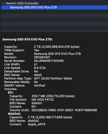
Blade upgrade: 32GB Blade ->
2TB Samsung 970 EVO NVMe SSD
HDD upgrade: 1TB SATA HDD -> 1TB Samsung 960 EVO SATA SSD
Speed test: blade 2500 MB/s write, 3000 MB/s read, SATA SSD 450-ish
OS: Mojave 10.14.5
Adapter: Sintech ST-NGFF2013-C
with additional Kapton tape, OWC temperature sensor not used
Issues after fresh OS install and restore: NONE, No sleep or hibernate issues
Boot ROM Version:
172.0.0.0.0
SMC Version (system): 2.41f1
Although upgrading the iMac is straightforward and relatively easy, there are
(3) main potential installation problems which can lead to an inoperable and damaged iMac.
1. Screen falling off after reassembly, usually due to incorrect display adhesive strip application or use of cheap non-OEM after-market adhesive strips which can fail several days to months after iMac screen reassembly.
2. Incorrect installation of CPU with the overly high tension CPU mounting spring, resulting in bending of the CPU wafer board and possibly damage to the logic board socket pins.
3. Faulty installation of the non-Apple NVME M.2 drive using the Sintech adapter, which can result in electrical shorting between the adapter's electrical "wiring" and the metal shield of the logic board NVME connector. In my case, this problem developed several days after a "successful" install.
I also added mistakes from other users experience resulting in damage to their iMacs during the upgrade process, the most costly of which include the screen, logic board, and CPU. It is my hope that this “guide” will help you succeed with your upgrade and prevent major damage to your computer. I will post pertinent pictures into this post below. Please feel free to add your upgrade pitfalls, tips, and advise to this post. Good luck.
Tools/Parts:
1. I used a long strip of painters tape, sticky side up, folded at each end to the table, to attach and spatially organize the screws during disassembly process. You can also label the tape with a pen by component, such as left speaker, hard drive assembly, power supply, cooler, logic board, wifi, and right speaker. This organization facilitates quick reassembly. Alternatively, you could use the magnetic project mat by ifixit, as seen in the first repair video below.
https://www.ifixit.com/Store/Tools/Magnetic-Project-Mat/IF145-167?o=4
https://www.amazon.com/Magnetic-Pro...ACECT32M1RK&psc=1&refRID=04YK8W894ACECT32M1RK
2. Toolkits:
iFixit Manta Driver Kit - High quality toolkit which includes a wide assortment of 112 steel bits, highly recommended
https://www.ifixit.com/Store/Tools/Manta-Driver-Kit--112-Bit-Driver-Kit/IF145-392
https://www.amazon.com/iFixit-Manta-Driver-Kit-Piece/dp/B07BMM74FD/ref=sr_1_1_sspa?crid=ECSB62CHVP1O&keywords=manta+driver+kit&qid=1557054516&s=hi&sprefix=manta+,tools,160&sr=1-1-catcorr-spons&psc=1
iFixit Pro Tech Toolkit
https://www.ifixit.com/Store/Tools/Pro-Tech-Toolkit/IF145-307
LB1 High Performance Electronics Precision Repair Tool Kit (54 Piece Kit) - Top notch toolkit. This kit includes the T20, T10, T8, and T5 tips needed for servicing. T25 bit not included in this kit. The included T20 bit however works just fine with the T25 standoffs discussed below.
https://www.amazon.com/gp/product/B01DAWZ3ZG/ref=ppx_yo_dt_b_asin_title_o07_s00?ie=UTF8&psc=1
3. Odyson - Two-in-One Service Wedge Repair Tool Replacement for iMac 21.5" & 27" (Late 2009-Mid 2017) - This wedge perfectly stabilizes and slants the computer case back to make for easy repairs. Highly recommended. You can also use a small pillow.
https://www.amazon.com/gp/product/B0781GF4MR/ref=ppx_yo_dt_b_asin_title_o08_s00?ie=UTF8&psc=1
4. OWC in-Line Digital Thermal Sensor HDD Upgrade Cable and Install Tools for iMac 2012, (OWCDIYIMACHDD12)
https://www.amazon.com/gp/product/B00J42HP9O/ref=ppx_yo_dt_b_asin_title_o03_s00?ie=UTF8&psc=1
This kit includes:
- (1) OWC In-line Digital Thermal Sensor Cable
- (1) Cutting wheel to cut display adhesive
- (2) OWC 2-1/4" Suction Cup
- (1) Torx T10S Driver
- (1) Torx T8S Driver
- (1) Nylon Pry Tool (Spudger)
- (1) Set of Adhesive strips
- (1) OWC Blue Microfiber Screen Cleaning Cloth
These tools and parts can also be purchased individually:
https://www.amazon.com/Opening-Hand...ing+wheel&qid=1556435379&s=electronics&sr=1-2
This In-Line Digital Thermal Sensor HDD Upgrade Cable device is presumably necessary to prevent cooler fan from going continuously full blast. I however did not need this device and suffered no problems with the fan going continuously full blast without the device. Again, I experienced no problems without the OWC device, with removal of both fusion SSD and hard drive components.
I personally would avoid this use of these adhesive strips as there have been multiple reports of screens falling off after reassembly, a very costly problem. Read the multiple negative Amazon reviews of this product regarding adhesive strips failing, with screens falling off and breaking.
https://www.amazon.com/OWC-Digital-...e=all_reviews&pageNumber=1#reviews-filter-bar
5. Painter’s tape for securing bottom edge of screen during testing and reassembly. See post #3 pictures.
https://www.amazon.com/ScotchBlue-P...e&qid=1557760855&s=gateway&sr=8-1-spons&psc=1
6. Spudger - Highly useful tool to help pry off very small connectors. Don’t pull on cable to remove connector as this may damage cable and/or connector.
DO NOT USE THE GREEN OR BLACK SPUDGER DEVICES TO PRY OFF SCREEN! This will result in cracking of the very thin delicate display glass!
https://www.ifixit.com/Store/Tools/Spudger/IF145-002?o=2
https://www.ifixit.com/Store/Tools/Spudger-Retail-3-Pack/IF145-334?o=1
7. NewerTech AdaptaDrive 2.5" to 3.5" Drive Converter Bracket - One of the best brackets to mount 2.5” SSD SATA drive in existing hard drive assembly. Very well made.
https://www.amazon.com/gp/product/B005PZDVF6/ref=ppx_yo_dt_b_asin_title_o09_s00?ie=UTF8&psc=1
8.
NVME Adapter Update:
Don't use this short adapter (ST-NGFF2013).
https://www.amazon.com/gp/product/B07FYY3H5F/ref=ppx_yo_dt_b_asin_title_o08_s00?ie=UTF8&psc=1 Sintech NGFF M.2 nVME SSD Adapter Card for Upgrade MacBook Air(2013-2016 Year) and Mac PRO(Late 2013-2015 Year)
Instead, use this long black adapter version (ST-NGFF2013C), with additional Kapton tape
https://www.amazon.com/gp/product/B01CWWAENG/ref=ppx_yo_dt_b_asin_title_o04_s00?ie=UTF8&psc=1
http://eshop.sintech.cn/ngff-m2-pcie-ssd-card-as-2013-2014-2015-macbook-ssd-p-1229.html
Sintech NGFF M.2 nVME SSD Adapter Card for Upgrade 2013-2015 Year Macs(Not Fit Early 2013 MacBook Pro)
This is the adapter used to convert conventional the M.2 NVMe connector to Apple proprietary connector. Be sure your adapter has insulation tape at the Apple end of the adapter to prevent electrical shorting with metallic shroud on logic board M.2 SSD connector.
Update: I ended using the long black adapter version of the Sintech adapter
(ST-NGFF2013C).
I was only able to get a slower Link Width x2 speed with the short adapter,
ST-NGFF2013, and successfully achieved a faster Link Width x 4 speed with the longer adapter,
ST-NGFF2013C.
The longer adapter likely promotes better alignment of the contacts. The shorter adapter/NVME combo fits tightly on logic board and demonstrated peeling back of the adapter's insulating tape. This may result in suboptimal alignment and possible shorting of connector contacts, and thus slower negotiated speed. See posts #28 and 33.
9. Thin Card to help pry adhesive tape holding screen in place. I just used the cutting wheel.
https://www.ifixit.com/Store/Tools/Plastic-Cards/IF145-101?o=1
10. Microfiber cloth - multiple uses
https://www.amazon.com/MagicFiber-M...d=1557660942&s=electronics&sr=1-1-spons&psc=1
11. Thermal Paste - Arctic Silver 5 or Arctic MX-4.
https://www.amazon.com/gp/product/B00LT0ZWJE/ref=ppx_yo_dt_b_asin_title_o08_s00?ie=UTF8&psc=1
https://www.amazon.com/gp/product/B0795DP124/ref=ppx_yo_dt_b_asin_title_o07_s00?ie=UTF8&psc=1
12. EKWB EK-M.2 NVMe Heatsink- Black
https://www.amazon.com/gp/product/B073RHHYCM/ref=ppx_yo_dt_b_asin_title_o00_s00?ie=UTF8&psc=1
13. Vanilla 2-inch no residue masking/painter's tape for multiple uses as discussed below.
https://www.amazon.com/No-Residue-E...&qid=1555694020&s=gateway&sr=8-33-spons&psc=1
14. Samsung 970 EVO 2TB - NVMe PCIe M.2 2280 SSD (MZ-V7E2T0BW), Black/Red
https://www.amazon.com/gp/product/B07C8Y31G1/ref=ppx_yo_dt_b_asin_title_o03_s00?ie=UTF8&psc=1
The 970 EVO drive is based on M.2 2280 design, that is, it measures
22 mm wide and 80 mm long and uses x4 PCIe Gen 3 to connect to the host computer.
No current upgradeable firmware via Magician Software since Apr 2018
Update from Zach on iFixit.com: Zach had trouble with the following NVMe drives on his new 2019 27-inch iMac:
https://www.ifixit.com/Answers/View...ades:+2019+vs+2017+27-inch+iMacs#answer568985
- 1TB WD Black drive
- 1TB 970 EVO Pro drive
15. Apple proprietary NVME drives.
https://beetstech.com/product/sspolaris-ssd-256gb-512gb-1tb-2tb
16. Samsung 860 EVO 1TB 2.5 Inch SATA III Internal SSD (MZ-76E1T0B/AM)
https://www.amazon.com/Samsung-Inch...+sata+ssd+860&qid=1555837192&s=gateway&sr=8-3
17. Intel Core i7-7700 Desktop Processor 4 Cores up to 4.2 GHz LGA 1151 100/200 Series 65W
https://www.amazon.com/gp/product/B01N0L41N7/ref=ppx_yo_dt_b_asin_title_o00_s00?ie=UTF8&psc=1
18. NEW Apple 076-00332 LCD Adhesive Strips, iMac 27” 2017 Retina 5K A1419 VHB (Very High Bond) Adhesive Strips
https://www.ebay.com/itm/NEW-Apple-...ugAAOSwdilcn4so:sc:USPSFirstClass!46060!US!-1
https://www.ebay.com/itm/x20-NEW-Apple-076-00332-LCD-Adhesive-Strips-iMac-27-2017-Retina-5K-A1419/332439434940?ssPageName=STRK:MEBIDX:IT&_trksid=p2057872.m2749.l2649
https://www.ifixit.com/Store/Tools/3M-Double-Sided-Adhesive-Tape--2-mm-Width/IF145-283?o=1
19. I will be testing this 3M 94 Tape Primer.
https://www.ifixit.com/Store/Tools/Primer-94/IF317-076?o=1
https://www.amazon.com/3M-Primer-3-...GKBV8VMN9KM&psc=1&refRID=M5S70STH2GKBV8VMN9KM
https://www.amazon.com/New-Hi-Transparent-Adhesion-Promoter-Adhesive/dp/B07D8FFX19
20. Magnetic telescoping screw pickup tool.
The Manta Drive Kit listed above includes a magnetic pick up bit.
Slim 25” Durable Telescoping Magnetic Grabber/Retrieving Magnet with Pocket Clip (07228)
https://www.amazon.com/Master-Magne...3Q0FAGPVR65&psc=1&refRID=3G7H38BJG3Q0FAGPVR65
https://www.ifixit.com/Store/Tools/Magnetic-Pickup-Tool/IF145-078?o=2
21. NVME screw - I ended up using one of the included screws (M2 6mm) which came with the Sabrent NVME drive enclosure, which fit perfectly. The stock Apple screw did not fit as well. See post #25.
22. Consider Anti-Static ESD mat and wrist strap to prevent damage related to static electricity.
https://www.ifixit.com/Store/Tools/Anti-Static-Mat/IF145-036?o=1
https://www.ifixit.com/Store/Tools/Anti-Static-Wrist-Strap/IF145-071?o=1
23.
Kapton Tape - Polyimide High Temperature Resistant Tape
https://www.amazon.com/gp/product/B072Z92QZ2/ref=ppx_yo_dt_b_asin_title_o05_s00?ie=UTF8&psc=1
https://www.macpartsdepot.com/922-1731-macs-kapton-tape-0-5-inch-by-36-yards.html
https://en.wikipedia.org/wiki/Kapton
24. Heat gun - used to heat adhesive strips during display reassembly for "better" bond
https://www.ifixit.com/Store/Tools/Heat-Gun/IF145-031?o=1
https://www.amazon.com/gp/product/B07NG78Q31/ref=ppx_yo_dt_b_asin_title_o01_s00?ie=UTF8&psc=1
The heat gun is used by some repair shops. Probably not recommended since excess heat could damage screen electronics.
25. 923-01322 Antenna tool - (not necessary, but helps)
https://www.ebay.com/itm/2PK-Antenn...-Pro-13-Part-923-01322-92301322-/113667617401
26. ESD-safe tweezers -
https://www.amazon.com/Kingsdun-Pre...safe+tweezers&qid=1557583611&s=gateway&sr=8-4
27. Tech Spray Wipes Isopropyl Alcohol 99% Pure 50/Pack
https://www.amazon.com/Tech-Spray-W...echspray+1610&qid=1557586849&s=gateway&sr=8-4
28. Silicone Display Roller - 922-8261
Alternatively, you can apply pressure with a microfiber cloth to the areas with adhesive strips.
https://www.amazon.com/Aexit-Manual...ler+silicone&qid=1557653892&s=gateway&sr=8-65
Be sure to cover aluminum frame with tape to prevent scratching of glass screen.
29. Apple Nylon Probe/Spudger Tool (Black Stick) 922-5065
https://www.amazon.com/Apple-Nylon-...ords=922-5065&qid=1557656077&s=gateway&sr=8-5
30. Display extension cable set (076-00010) for iMac (Retina 5K, 27-inch, Late 2014–2017)
https://www.ebay.com/itm/NEW-076-00...e-Set-for-iMacRetina-5K-27-2017-/173130361968
Not necessary, allows you to:
- test the system and/or panel before securing the panel to the very high bond (VHB) adhesive strips.
- test the functionality of the panel’s Embedded DisplayPort (eDP) cable.
Apple Flash Storage:
661-07311, 32GB
661-07312, 128GB
661-07315, 256GB
661-07317, 512GB
661-07319, 1TB
661-07320, 2TB
Repair/Teardown Guides and Upgrade YouTube Videos:
1.
Excellent video showing all steps.
2.
https://www.ifixit.com/Guide/iMac+Intel+27-Inch+Retina+5K+Display+CPU+Replacement/30515 ifixit guide showing disassembly. The 2015 27-inch iMac guide is virtually identical to the 2017 27-inch iMac except for the addition of a new tiny ribbon microphone cable at the bottom right of the logic board and a new mounting system for the WIFI cables.
3.
.
4.
How to apply adhesive strips
5.
.
6. -
7. -
8.
.
9.
.
10.
.
11.
.
12.
.
13.
.
14.
https://www.youtube.com/watch?v=JYXURhQrueU The 2017 27-inch model now uses T8 screws for the power supply, logic board, and NVME drive. They forgot to plug in some usb cables into the back side of the iMac to ensure proper port alignment prior to logic board reassembly. WIFI connector cables are now secured in the 2017 model by metal tabs, held by (2) T5 screws.
15.
16.
17. Thermal Cooling pads, for use on VRMs.
https://www.ebay.com/i/173872862487?chn=ps&var=472593568183
http://vi.raptor.ebaydesc.com/ws/eB...171&category=181907&pm=1&ds=0&t=1556169129434
https://es.aliexpress.com/item/Alta...241.html?spm=a2g0s.9042311.0.0.3c7063c00W75L3
18.
19.
iMac Upgrade FAQs:
https://everymac.com/systems/apple/...grade-imac-hard-drive-aluminum-2012-2013.html
Screws:
- T25: Metal Spacers/Standoffs (I ended up using an available T20 bit which worked just fine)
- T10: Speakers, CPU Mounting Spring, Cooler Fan, (2) upper Heatsink screws
- T8: Hard Drive brackets, Pins on Hard Drive, Power Supply, Logic Board, GPU bracket, SSD NVME
- T5: WIFI
- PH00: Small Phillips screws holding bottom "trim". I didn't remove the trim. You can just loosen and push speakers out of the way without removing the speakers from the chassis.
MacOS Operating System Installation on New Drives and Recommended Supportive Hardware:
1. Cloning software:
https://bombich.com - Carbon Copy Cloner - time proven cloning software
2.
https://eshop.macsales.com/guides/Cloning-Your-Data-to-a-New-Hard-Drive
I used the simpler Carbon Copy Cloner method to clone my drive.
3.
4. Sabrent USB 3.1 Aluminum Enclosure for M.2 NVMe SSD in Gray (EC-NVME) - I used this excellent very fast enclosure to copy my drive image to the NVME drive. It however is not compatible with the Samsung Magician software needed to update Samsung M.2 NVMe drive firmware. You can use a Thunderbolt 3 to M.2 NVMe adapter/enclosure for firmware updating.
https://www.amazon.com/Sabrent-Alum...+3.1&qid=1555094958&s=gateway&sr=8-3-fkmrnull
5. Sabrent USB 3.1 (Type-A) to SSD / 2.5-Inch SATA Hard Drive Adapter
After initializing, erasing/reformating the drive to APFS filesystem and GUID map/table, and renaming the drive to Macintosh HD with the Disk Utility, I used this drive to copy the boot drive to this SATA SSD drive. I have it setup so that I can boot from either the NVME or SSD SATA drive after pressing the “option” key during restart of the computer.
https://www.amazon.com/Sabrent-2-5-...+3.1+sabrent&qid=1555095227&s=gateway&sr=8-16
6. How to reinstall macOS from macOS Recovery (using network to download macOS installer)
If you are installing a fresh Mojave install and don't want to use a separate bootable USB drive for the new macOS installation, you can also install macOS from macOS Recovery to the latest macOS using a
network connection after booting using the:
Option-⌘-R (Upgrade to the latest macOS compatible with your Mac) key combination.
First use Disk Utility to erase and format your disk to:
Name: Macintosh HD
Format: APFS
Scheme: GUID Partition Map
https://support.apple.com/en-us/HT208496
Then:
Choose Reinstall macOS (or Reinstall OS X) from the Utilities window.
Click Continue, then follow the onscreen instructions to choose your disk and begin installation.
https://support.apple.com/en-us/HT204904
7. How to create a bootable installer for macOS
https://support.apple.com/en-us/HT201372
8. Consider disabling SIP (System Integrity Protect) on the bootable drive. Command: csrutil disable
9. Be sure to backup all you data.
10. Trim is automatically enabled for NVMe drives by default.
Trim is enabled with the following command (not necessary with NVMe drive, again enabled automatically):
sudo trimforce enable
http://osxdaily.com/2015/10/29/use-trimforce-trim-ssd-mac-os-x/
Trim Enabler software - You may need this to enable Trim on a SATA SSD drive.
https://cindori.org/trimenabler/
11. Mac startup key combinations
https://support.apple.com/en-us/HT201255
12. You will need to update your iMac to Sierra (10.13+) or Mojave to install the latest iMac firmware update that will allow the NVMe drive to be supported.
Consider updating to Sierra or Mojave before performing the hardware upgrade.
My current firmware version:
Boot ROM Version: 172.0.0.0.0
SMC Version (system): 2.41f1
Screen Removal and Reassembly with Adhesive Strips:
1. Before starting repair:
- Turn off the computer.
- Unplug the power cord from the electrical outlet.
- Disconnect all cables.
- Put on an ESD wrist strap and attach it to a properly grounded ESD mat.
Don’t try to use a suction method on the newer thin iMacs as it will almost always result in a cracked display. This only works on the older displays held in place by magnets.
Consider removing the screen while laying the computer down on a table as several users have accidentally dropped the screen on the table when removing screen in the upright position. This happened to Linus on YouTube after his tech was startled when the back of the screen made contact with the power supply causing a spark, resulting in dropping the screen. Expensive mistake.
2. Insert the display removal tool at a 90-degree angle (hold the display removal tool perpendicular to the edge of the computer) in the top left corner between the display and rear housing. Roll the tool across the top of the computer, avoiding the 3-inch area surrounding the camera. The tool should only be used along the top and sides of the display, not along the chin.
Be sure to use the cutting wheel to cut the adhesive tape holding the display in place in a straight line, with back and forth cutting. Do not torque or try to pry screen off with tool as you can crack the glass. Use your hands to gently pry the display off after the adhesive strips have been cut. Do not use the green or black spudgers to pry off screen as this can result in cracking your glass display. Avoid pulling too hard on suction cups as there is at least one YouTuber who bent his display with too much force. I did not use the suction cups. I just used the cutting wheel and my fingers to gently pry open the display.
3. Use a service wedge to secure computer in place to fix computer in a slanted back position.
4.
Use Apple OEM adhesive to reapply screen. There are multiple forum posts and Amazon reviews of failed adhesive strips and videos discussing use of incorrectly applied or cheap after market adhesive tapes failing. This can result in screen coming loose and falling onto table, resulting in possible damage to the screen, display cables, and logic board.
https://forums.macrumors.com/threads/worlds-saddest-mac-story-or-how-i-royally-screwed-things-up.2179105/
https://www.amazon.com/OWC-Digital-...e=all_reviews&pageNumber=1#reviews-filter-bar
5. After removal of screen during disassembly, completely remove all residual strips and clean off residual sticky adhesive with greater than 90% isopropyl alcohol (IPA) and lint-free cloth.
Do not peel VHB from the display corners. The chance of damaging the black Mylar protective film is greater if VHB removal is started in the corner.
Wipe IPA wipes in one direction, not back and forth. The surface needs to be clean and dry prior to adhesive tape reapplication.
Use an IPA (isopropyl alcohol) wipe (at the end of a flat spudger tool) to remove any remaining adhesive from the rear housing and display edges. Allow the surfaces to dry for 1 minute.
https://www.ifixit.com/Answers/View...r+Repair+-+New+Adhesive+Not+Sticking+Properly
6. Consider adding small velcro pads to the front of speakers - back of display as a secondary protection in case the adhesive strips fail.
7. Add a strip of tape to the lower edge of the screen during disassembly to prevent accidental slippage of the screen during removal. I used gorilla clear double sided tape which leaves no residue and ensures a very strong bond. I also used multiple small pieces of the tape on the outside of the screen to keep the iMac display in place for testing, prior to final sealing with adhesive strips.
8. Consider applying prolonged compression to the screen after the application of adhesive strips to ensure a good bond. You can use some plastic clamps on top of thin books with gently pressure or lay computer down and place some books on the screen to apply some gentle downward pressure.
9. When prying off screen, avoid stretching the screen power and data cables. The screen data cable has a wire locking latch that needs to be flipped back prior to unseating cable. Gently pry the screen power cable with a spudger tool at the connector. Avoid pulling back on cable as this may damage cable and/or connector.
10. Be sure to use OEM adhesive strips to ensure easy future removal of screen. These strips contain foam which allows for easy cutting. Use of nonstandard non-foam strips with excessive adhesion can lead to great difficultly removing screen and possibly a cracked screen if you are forced to use excessive prying force. I’d rather have temporary pieces of tape holding the outside of the display in place for a few weeks to confirm successful adhesive tape application. There are reports of the adhesive strips failing up to six months after reapplication!
https://forums.macrumors.com/threads/broken-screen-27”-pics.2128286/#post-26266424
11. Keep your work surface free of any tools such as screw drivers as you remove your screen as you can crack the fragile screen by resting it on a screw driver.
12. Screen Replacements:
http://www.ifixmaccomputers.com/imac-27-inch-5k-mid-2017-lcd-panel-assembly-replacement-apple-661-07323?search=iMac 27-inch 5K, Mid-2017
https://www.amazon.com/gp/product/B...SQ633&linkId=6fe4a39e58ca5fc125432d1778f57a36
13. Use painter's tape or masking tape to temporarily secure the bottom edge of the display to the iMac's enclosure. The tape preserves the display's alignment, and allows you to safely swing the top edge of the display open to access the display cables.
14. When reattaching display with adhesives, ensure the display is along the bottom edge of the chassis as flush with the lip, as centered as possible, avoiding any gap. Don't let the display close yet as you need to reconnect the video cables. Before lowering the screen in place, you want to first plug in and power up iMac to make sure that it boots without issue. After checking, power down the system before making any adjustments or completing the installation. You can now carefully lower the display into place, making sure you have the edges lined up correctly. Then gently squeeze along the edges to make sure the adhesive sticks. Use the microfiber cloth to remove any finger prints or suction marks.
15.
https://www.ifixit.com/Guide/iMac+Intel+27-Inch+EMC+2546+Adhesive+Strips+Replacement/15624
16. Consider use of multiple A-clamps to clamp around the edge of the screen, overnight, to ensure good adhesive bonding.
https://www.mac-forums.com/forums/apple-desktops/346491-imac-screen-fell.html
17.
https://ifixit-guide-pdfs.s3.amazonaws.com/pdf/ifixit/guide_24341_en.pdf
18. Given the potential of delay problems that can make your iMac unstable or inoperable (such as the NVME/adapter assembly), consider delaying application of the adhesive strips after the computer has been stable and up and running for at least a week. In the meantime, you can apply strong adhesive non-residue tape to keep the display in place.
19. Be sure to check that you have reconnected all of the internal cables prior to re-applying the display.
20. Use the
silicone display roller to adhere the display adhesive strips (
on the sides of the display) to the glass. To prevent image quality issues, only roll upward. Roll the silicone display roller
along the top in a horizontal back-and-forth motion.
21. Lay out the adhesive strips and inspect them for damage, wrinkles, or exposed sections. Damage can cause cosmetic gaps and leakage and weaken the bond.
22. If a display adhesive strip does not line up correctly, remove it, clean the rear housing, and start again. Ensure there are no wrinkles or exposed sections on the strip.
23. Be careful when removing VHB from the display panel. To prevent damage to the black Mylar protective film that is located on the display panel glass, ensure that you are peeling up the VHB and not the Mylar film. An easy way to ensure that you do not peel up the Mylar film on the display is to start peeling the VHB from the center points, not from the corners of the display.
24. During screen reassembly, the bottom right adhesive strip labeled
25 for iMac (2017) has a
perforation in the VHB for the microphone hole, refer to image below (see post below). Make sure to use the correct strip and
line up the perforation with the microphone hole or it could lead to microphone issues [that is, poor muffled recording sound quality].
Disconnecting Logic Board Cables/Cable Management:
1. Do not pull on the tab on the tiny thin ribbon cable (microphone cable) at the bottom right of the logic board. The tab will avulse/rip off. Mine did.

Use your spudger tool to gently pry and slip off connector. Take your time. Again, do not pull back on cable or tab. The tab is only used to position the cable back into it’s connector during reassembly.
2. Tape down microphone ribbon cable to front of case to keep cable out of the way, during logic board reassembly.
3. The power supply connectors on the back of the power supply board both have locking latches that need to be depressed in order to remove the connector.
4. Consider using tape to label the order of WIFI connectors. You can also take a picture with your cell phone to note the correct order. The picture provided in posts below show the correct order of cables.
5. Again, remember to detach the
metallic wire latches (known as "Locking Lever Bails") that secure the Display Data Cable and iSight Camera Cable.
CPU and Heatsink Reassembly:
1. Forum posts and YouTube videos documenting the bent CPU problem.
-
Footnote #3: A little drama that wasn't included in the video is that the first time around, the CPU got bumped out of the socket when I screwed in the cooler, so the CPU wasn't seated correctly and the computer didn't boot. Upon disassembling the machine again, I saw the CPU was out of the socket and partially bent. I bent the CPU back (silicon bends easily without damaging, luckily), reinserted it into the socket, and was more careful when I tightened the CPU cooler the second time. It's easy to wiggle the CPU out of place when installing the cooler, so be careful—and if it feels too hard to tighten the CPU socket, stop—something is wrong.
-
bent cpu mistake discussed at 3:57 in the video
-
#23
-
https://forums.macrumors.com/thread...017-ssd-upgrades.2162435/page-2#post-27115420
- Multiple users, including myself, have fallen into the trap of incorrectly reassembling the CPU spring (single "Leaf Spring") and heatsink to the logic board. I was aware of this problem and still screwed it up.
In my opinion, the CPU spring tension is very excessive. Ideally, two people could perform the installation as in one of the videos. Note that (2) of the screws on the same side of the spring are secured first, followed by pressing down spring and securing the 3rd and 4th screws. Others have installed the screws diagonally. Given the high tension of the spring, it is too easy to misalign the CPU in the reassembly process. Also, you will likely literally bend your CPU if you screw the screws all the way down. You should probably only screw the screws partially, no more than half-way down. My solution was to remove some of the excessive tension by removing some of the extreme bend by bending/partially straightening the spring in a wood vise/clamp. This resulted in less spring tension and more optimal alignment of the screw holes of the spring so that the screws could be easily anchored by hand prior to final tightening. You can always re-bend the spring back if necessary. I still had more than enough spring tension after the spring modification. I have had no CPU problems.
2. If you are gun shy about bending your CPU Spring, you can order a used backup spring on Ebay. Look up iMac Heatsinks on Ebay.
3. Place some painter’s tape on the GPU mounting bracket on the backside of the logic board to keep the GPU bracket held in place and aligned with the screw holes after removal of screws. This can save you a little time with realignment when reassembling the CPU/GPU.
4. Avoid too much thermal paste.
5. One person’s advise: Do not over-tighten the CPU. If you look under the board, you don’t want to see the base of the screw coming through the hole or you are going too tight.
6. Diagnostic LEDs: "If you only have one green led [LED 1], search for some mistake, any bad connection, power supply not connected or the CPU not seated correctly in the socket. My problem was the CPU was incorrectly seated."
7. Securing GPU bracket first during heatsink reassembly will help to align and minimize movement of the heatsink assembly during CPU spring tightening.
Speakers:
1. Consider removing the bottom trim (Apple calls this the "Chin Strap") held by Phillips screws to aid in speaker removal.
https://www.youtube.com/watch?v=YSgcJH5bdWM. This isn’t necessary, but makes it easier to remove speakers. I left my in place with no problem. You just have to apply a little more effort.
2. When removing left speaker, be sure to remove recessed cable for "power button" prior to complete removal of left speaker as you can easily rip out cable.
3. Be sure to fit “power button” cable into the recessed groove of the left speaker prior to reassembly of left speaker into case.
4. Regarding right speaker reassembly, connect the right speaker connector prior to final alignment and mounting of right speaker.
5. Avoid touching small speaker domes and tiny tweeters during disassembly and reassembly as they can be easily damaged.
Hard Drive Assembly:
1. The right hard drive bracket lower screw does not have to be removed. This allows you to flip bracket out of the way.
2. The SATA cable runs above cpu heatsink exhaust duct and under the right hard drive bracket.
3. The hard drive assembly has to be reinstalled before the left speaker.
4. The right hard drive bracket lower screw/spacer has to be installed before logic board.
5. Don't forget to remove the (4) T8 mounting hard drive pins/pegs from the 3.5" spinning hard drive, which slide into the rubber grommets of the hard drive brackets.
Cooler Assembly:
1. Consider blowing dust out of cooler assembly.
2. Don’t forget to pull the heatsink duct adhesive flap (black Mylar shield) in front of and on top of cooler and reapply adhesive flap to cooler to maintain a good seal.
Power Supply (300W):
1. Avoid touching contacts.
2. Depress connector latches/tabs on back of power supply to remove connectors as above.
3.
http://www.ifixmaccomputers.com/661-03524-apple-power-supply-imac-27inch-late-2015-a1419?search=iMac 27-inch 5K, Mid-2017
4. The spacer with the shorter screw stem is used to bolt down the left black flange of the heatsink duct/logic board. The top right power supply screw then screws into this spacer.
5. Consider applying a taped temporary sheet of "insulating" paper to the back of the power supply during disassembly/reassembly to prevent accidental electrical shorting with the metallic back surface of the display. This shouldn't happen if the bottom edge of the display is securely resting on the bottom of the iMac case ledge. This is however how Linus's tech broke their screen as mentioned above.
6. When reassembling power supply, first connect the AC inlet cable along the bottom right of the front of the power supply.
7. The AC inlet cable should rest below the adjacent bottom right spacer/standoff.
8. I inserted a partially folder envelope between the power supply board and the case to prevent accidental shorting during removal and installation of the power supply.
9. The (2) long T8 screws mount the top of the power supply. The (2) short T8 screws mount the bottom of the power supply.
10.
https://beetstech.com/product/power-supply-300w-661-7886
Logic Board:
1. When reassembling the logic board, first secure logic board with central captive screw (located inside the hole) partially tightened. The tool kit screw-driver listed above fits perfectly into this hole. This captive screw corresponds to the screw along the black right heatsink duct tab. Then plug in test USB, thunderbolt, and network cables to properly align the logic board ports with corresponding cutouts in the case housing, and then apply and tighten logic board screws. One guy had to take apart his iMac again since the ports did not line up the the case slots after reassembly. This is clearly showed in the videos/guides above.
2. Consider use of 1mm thermal pads for the VRMs as in this video instead of thermal paste.
https://www.youtube.com/watch?v=HZIiF4fczYA. I just used Arctic Silver 5 paste.
3. Be sure to note how the long spacer/standoff (with short stem screw) anchors the left black tab off the Heatsink assembly. The upper right screw of the power supply then screws into this standoff.
4. The spacer with the longer screw stem bolts down the bottom hole of the right hard drive bracket. This spacer can be loosened but left in place during disassembly. The leftmost logic board screw then screws into this spacer.
5. Use the flat portion of the spudger to gently pry off the WIFI connectors. See picture below.
6.
http://www.ifixmaccomputers.com/ima...-2ghz-logic-board-replacement-apple-661-03383
7. For the (2) T8 screws on the top of the heatsink duct, consider using the "flexible screw driver" since the screws are difficult to engage given the limited space.
8. Caution: Do not lift the flash storage card at an angle when removing it from the connector. If you damage the connector, you must replace the logic board.
9. Pay special attention to the areas in the images below when handling the logic board. Mishandling the logic board can damage chips and circuits. Components that accidentally touch the rear housing may damage the computer and keep it from operating correctly.
NVME drive/Heatsink/Sintech Long Black Adapter Assembly
I HIGHLY recommend you use Kapton tape to insulate the Sintech long black NVME adapter.
Please see post #33
Disk Benchmark Software:
1. AJA System Test
https://www.aja.com/products/aja-system-test
2. Blackmagic Disk Speed Test
https://itunes.apple.com/us/app/blackmagic-disk-speed-test/id425264550?mt=12
3. AmorphousDiskMark -
http://www.katsurashareware.com/pgs/adm.html - click download in upper left of page.
4. Intech SpeedTools -
https://eshop.macsales.com/item/Intech Software/STTPRO/
Graphics Benchmarks:
1. Cinebench -
https://www.maxon.net/en/products/cinebench-r20-overview/
2. Heaven -
https://benchmark.unigine.com/heaven?lang=en#editions
General Benchmarks:
1. GeekBench 4 -
https://www.geekbench.com/
General Utilities:
1. Intel Power Gadget -
https://software.intel.com/en-us/articles/intel-power-gadget-20
2. Drive Dx -
https://binaryfruit.com/drivedx
3. TRIM Enabler 4 -
https://cindori.org/trimenabler/
4. diglloydtools -
https://diglloydtools.com/
5. MacCPUID -
https://software.intel.com/en-us/file/maccpuiddmg
Magician Software for Samsung NVMe drive:
-
https://www.samsung.com/semiconductor/minisite/ssd/product/consumer/magician/
- https://www.storagereview.com/samsung_magician_and_data_migration_overview
- Overprovisioning is just a way to simply prevent you from overfilling your drive to an extent that it bogs down your drives performance. Even NvME drives and such can be bogged down if there's too much data on them, so simply put, 10% OP will just prevent you from utilizing that last 10% available storage on the drive, allowing the system to fully utilize the performance of the drive without it being slowed down by overloading of data.
- Rapid Mode is only supported on Windows and SATA SSDs
Diagnostic Tests/Verification of successful upgrade:
1.
https://support.apple.com/en-us/HT202731
2. Reference codes:
https://support.apple.com/en-us/HT203747
3. How to Verify Your Mac’s Hardware Is Working Properly -
https://www.intego.com/mac-security-blog/how-to-verify-your-macs-hardware-is-working-properly/
4. Go to
‘About this Mac’ -> ‘System Report’ -> NVMExpress, make sure you see
Link Width: x4, some have reported the slower Link Width: x2. This causes sub-optimal read/write speed, and is most likely secondary to a bad adapter.
5. Activity Monitor - consider
Content Caching enabled in the Sharing pane of System Preferences
https://support.apple.com/en-us/HT201464#memory
Troubleshooting:
1. Reset SMC -
https://support.apple.com/en-us/HT201295
Ram issues? Reset SMC -
https://forums.macrumors.com/threads/2017-imac-ram-issues.2182398/#post-27387165
2. Reset PRAM & NVRAM -
https://support.apple.com/en-us/HT204063
3. Start up in safe mode -
https://support.apple.com/en-us/HT201262
5K Retina 27-inch iMac
Service Manuals (The original Step-by-Step technical guides which Apple provides for Mac-certified technicians and the videos as a part of Apple training course for qualified Mac technicians):
- 2017
Manual Only,
https://www.ebay.com/itm/iMac-27-in...598326?hash=item1ef01f3e76:g:maYAAOSwc6ZcBtbr
This is the actual 484 page service manual Apple provides to technicians. Costs $1.99 on Ebay, paid by PayPal. Authentic.
- 2017
Manual and videos,
https://www.ebay.com/itm/iMac-27-inch-Retina-5K-2017-Service-Technical-Guide-Video-Repairing-Course/132973174152?_trkparms=aid=333200&algo=COMP.MBE&ao=1&asc=20190129125700&meid=8152afdb8ff7486ba938f61cc35de598&pid=100752&rk=2&rkt=12&sd=132950790314&itm=132973174152&_trksid=p2047675.c100752.m1982
- 2019
Manual:
https://manuals.info.apple.com/MANUALS/1000/MA1859/en_US/imac-5k-27-inch-2019-repair.pdf
Diagnostic LEDs (total of 5) are located along the upper right side of the logic board, just to the right of the display data cable connector.
Diagnostic LEDs 1–5
1 = AC input voltage (trickle power present)
2 = Power supply DC output voltage
3 = Memory is functioning
4 = GPU is functioning
5 = Display panel is connected
Diagnostic LEDs
LED 1
- Indicates that the trickle voltage from the power supply has been detected by the main logic board. This LED will turn on when you connect the iMac to a working AC power source. The LED will remain on as long as the computer is on or asleep.
- When the computer has been shut down correctly, LED 1 behavior may differ:
- If a startup event is scheduled in System Preferences/Energy Saver, then LED 1 will stay on after a correct shutdown.
- If no startup event is scheduled in System Preferences/Energy Saver, then LED 1 will turn off and will stay off as long as the power cord is kept connected and an AC power source is present. Disconnecting the power cord and plugging it back in will turn this LED back on, even if the computer is still off.
- After disconnecting and reconnecting the AC power source, this LED could remain off:
- If the AC power source is missing or disconnected.
- If the logic board is disconnected from the power supply or the AC receptacle.
- If the power supply board is faulty.
LED 2
- Indicates that the computer is turned on. This LED will be on as long as the computer is turned on (but is not asleep) and the power supply and voltage regulators are working correctly.
LED 3
- Indicates that the logic board and GPU are communicating. This LED will be on when the CPU is communicating properly with the GPU. If LEDs 1 and 2 are on and LED 3 is off, then the backup battery (on the back of the logic board) may need to be reseated or the logic board may need replacement.
LED 4
- Indicates that the logic board and LCD panel are communicating. This LED will be on when the computer is turned on and a video signal is being generated. If LED 4 is on and there is no image on the display, then the LCD panel or the cables between the LCD and logic board might be installed incorrectly or need replacement.
LED 5
- Indicates the logic board and LCD panel are communicating. This LED is on when the computer is turned on, a video signal is being generated, and the LCD Panel is signaling to turn on the backlight. If LED 5 is ON and there is no image on the display, then the LCD backlight or circuitry on the logic board may be malfunctioning. The LCD panel or the cables or the logic board may need replacement.
LED Startup Sequence
LED 1 = Power is available.
If no LED is visible:
o Disconnect the power cord from the computer and wait 15 seconds to reset the power supply and LED status. Reconnect the power cord and check the LED status again.
o Verify the AC source.
o Verify that a known-good power cord is connected.
o Verify the cable connection between the AC inlet and the power supply.
o Verify the cable connection between the power supply and the logic board.
o Verify the power supply.
LED 1 + LED 2 = Power is available and the system is turned on.
If the second LED is not visible when the power button is pressed:
o Verify that the power button is connected to the power supply.
o Verify power button functionality.
o Verify the cable connection between the power supply and the logic board.
o Verify the power supply.
o Verify the logic board.
LED 1 + LED 2 + LED 3 = Power is available, the system is turned on, and the GPU was found.
If the third LED is not visible after the system is turned on:
o Verify whether the fan is running when turned on (reset SMC and PRAM, verify backup battery voltage for proper startup).
- If the fan is not heard, go to the “No Startup” troubleshooting flow.
LED 1 + LED 2 + LED 3 + LED 4 = Power is available, the system is turned on, the logic board is communicating with the GPU, and the internal LCD was found.
If the fourth LED is not visible after the system is turned on:
o Verify the internal DisplayPort cable (eDP) connections between the LCD panel and the logic board.
o Inspect the LCD display cables for cable damage.
o Verify external video functionality and proceed according to the result:
- If an external display works, verify/replace the LCD panel.
- If an external display does not work, verify/replace the logic board.
LED 1 + LED 2 + LED 3 + LED 4 + LED 5 = Power is available, system is turned on, GPU is working, logic board is communicating with the LCD panel, and the LCD panel has turned on the LCD backlight.
If the fifth LED is not visible after the computer is turned on:
o Verify the internal DisplayPort cable and backlight cable connections between the LCD panel and the logic board.
o Inspect the LCD display cables for cable damage.
o Using a flashlight, check the following areas on the panel:
- Look in the top left corner of the panel to see if there is a dim Apple logo (the Apple menu logo).
- Look in the center of the panel to see if there is a login screen.
- Look at the bottom of the panel to see if there is a Dock visible.
- If the following items are visible, there may be something wrong with the display cables or the logic board. Proceed to the next step.
- Replace the LCD panel, check that all the LEDs are visible, and that the backlight functions. If the computer does not function after replacing the LCD panel, replace the logic board.
Power-On Self-Test (POST)
Intel-based Mac computers such as the iMac rely on a combination of tones and blinking LED lights to display Power-On Self-Test (POST) error codes.
- If the computer detects out-of-specification or no Random-Access Memory (RAM), the screen will remain black but the computer will beep. This error condition may be due to physically damaged RAM, installing an incorrect type of RAM, or not having RAM installed.
- Some RAM may appear to pass POST, but still cannot be used by the operating system. In this case, the computer will display a gray screen, sound three beeps and repeat beeps until computer is turned off.
- The solution to both of these situations is to first reseat RAM and test computer again. If RAM fails POST again, remove all installed RAM and test by installing one by one each RAM module that has been verified to work correctly on another computer (“known-good” RAM, for example) or order new RAM.
- A sequence of tones heard at startup or a no video symptom may also be fixed by temporarily removing/replacing the backup battery.