Become a MacRumors Supporter for $50/year with no ads, ability to filter front page stories, and private forums.

peislander

macrumors member
Jun 17, 2011
84
0
P.E.I. Canada
I think those are actually ferrite beads rather than 0 ohm resistors but that is for EMI emissions reduction. You could safely use a zero ohm and the only effect would probably be higher interference with other devices (but probably not noticeable) :)

Yes your right again.I still have lots to learn.I think I replaced with regular zero ohm resistors & my friend has been using one for over a year now.Thanks for clearing this up.Cheers
 

Dadioh

macrumors 65816
Original poster
Feb 3, 2010
1,123
36
Canada Eh?
Yes your right again.I still have lots to learn.I think I replaced with regular zero ohm resistors & my friend has been using one for over a year now.Thanks for clearing this up.Cheers

The real question is... Can you listen to the radio sitting beside his Macbook? :D

No problem. I do EMI as part of my day job....
 

naKruul

macrumors newbie
Dec 25, 2011
25
0
hi again,

after getting my macbook backlight back to work i alrready mentioned it does not dither anymore (you can see the dimming steps). That's not a big problem, but in low light situations when the auto-dimming is active, the backlights tends to flicker between 2 dimming steps. That's kida annoying. I fchecked the available datasheets at TI but unfortunately there is no one available for the LP8550. But the LP855x series seem to be almost the same chips.
So i found the datasheet for the LP8552 here: http://www.ti.com/litv/pdf/snvs701
The dithering and PWM resolution can be set through i2c i believe. The I2C Interface is on SCLK (D3) and SDA (D4) Pins. Anyone have a clue how to programm that ****?

Greets
 

longcoo817

macrumors member
Oct 23, 2011
30
0
Dallas TX
mbp15_backlightret.jpg


Just to be sure are these the right return pin?
 

ecstrat286

macrumors newbie
Jan 25, 2012
2
0
chip orientation

Holy cow! guess what, my macbook is back on duty :)

i ordered the samples from NS and it took only 2 days shipping from singapore to germany with UPS Worldwide express. Thanks National :)

only thing i experienced is: the new chip does not have dithering, so you see the dimming steps. but thats a flaw i can live with.

thanks Dadioh for your support. and if anyone ever needs a LP8550 do not hesitate to contact me. or otherwise just get some samples from NS :)

I received my chip from National Semiconductor, but I'm not sure where Pin 1 is or which way the chip should face. Do you guys have a high resolution picture so I can see where the writing is in relation to the board? I just want to make sure i put it on in the right direction.

Thanks
 

naKruul

macrumors newbie
Dec 25, 2011
25
0
take the logic board an lay it in front of you. the display connector should be facing to the upper right. the RAM-slots are facing you.
You have to put the chip on the board in a way you can read the writings on the chip just normal.
This pic is from a macbook air:
6291601-850-568.jpg
Pin 1 is where the square mark is.
 

ecstrat286

macrumors newbie
Jan 25, 2012
2
0
take the logic board an lay it in front of you. the display connector should be facing to the upper right. the RAM-slots are facing you.
You have to put the chip on the board in a way you can read the writings on the chip just normal.
This pic is from a macbook air: Image Pin 1 is where the square mark is.

Thanks! Backlight is back! I appreciate your reply.
 

PJonHar

macrumors newbie
Dec 19, 2011
16
0
So i'm getting the 3.3V to turn the lcd on and i am getting the 24V to the backlight pins but i am still not getting an image on the screen and the backlights are not turning on. (It was a 0.1 ohm resistor R9730 that had blown).

It is as though the lcd isn't receiving the data signals, but when i connect it to an external monitor, an image is displayed.

any thoughts?
 

arakira

macrumors newbie
Jan 29, 2012
6
0
France
No backlight on my MacBook Pro early 2008 (A1260)

Hello everyone, and many thanks to all the contributors of this thread (I read and learnt a lot !).
I have an early 2008 macbook pro (LED, non-unibody) that seems to have a similar problem. After I broke my screen, I changed it myself, backlight still working but the screen I ordered was a defective one : strange lines were displayed on the screen. I tried to change the display and LVDS cable but stupidly I was too lazy to remove the battery between the tests... Suddenly backlight turned off. I returned the screen and ordered a new one, which now works except for the backlight. Everything else works perfectly (I can see the correct image with a strong light behind the screen, and external monitor works fine).
I tried three other LED driver boards, changed the cables, still no backlight. So I guess I fried something in the LED circuit during my tests. However on the early 2008 models I think this circuit is on the left I/O board (the LVDS cable is plugged to this board).
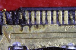
I read earlier in the thread that Peter (pseudo Poeter) has the same Macbook pro model and located the key components. If you are still around Peter, could you please help to locate the components on the board ? Or anyone else who tried the fix on the A1260 model ? I can provide close focus photos of the board if needed.
Also, the LVDS cable that provides power to the screen (plugged into the left I/O board) has 4 pins. Does anyone know the voltages supplied on this cable ? It would help me locate the culprit (in case I would have bought another defectuous screen !).
Any help would be welcome, many thanks !
 

arakira

macrumors newbie
Jan 29, 2012
6
0
France
Hello again, I have been looking further on the backlight problem of my early 2008 MBP.
First I realized I wrote a mistake : the LVDS cable is actually plugged into the logic board (not the left I/O board) ; the cable that powers the LED driver board, which has 5 pins, is something else (I don't know what is its name so I'll call it the LED power cable).

I wanted to check if the I/O board and LED power cable were functionning correctly and tested the voltages on the end of the LED power cable (just before the LED driver board). I read 0V from all pins. Then I tested them directly on the I/O board, and got the following :
pin 1 : GND
pin 2 : ranging from 0V to 3.15V, depending on the choice of screen backlight via F1-F2 keys
pin 3 : 3.27V
pin 4 : 12.59V
pin 5 : unused
Therefore I check the connector and find out that it is almost removed from the board... I'll have to have it resoldered properly.

If anyone has some knowledge about this model, I'd be very happy to know the following :
- given the voltages, I guess my left I/O board works correctly ? And given that the voltage on pin 2 responds to backlight keys, does it mean that my WLED circuit is OK ? Could there be another problem on the logic board where the WLED circuit is ?
And given that there are some eletronic experts here, do you know if there is a possibility that the electric shock that occured on my laptop could have damaged a connector (seems strange to me...) ?

Many thanks by advance ! I'll post the results after the resoldering, if anyone is interested.
 

PJonHar

macrumors newbie
Dec 19, 2011
16
0
So my backlight is working now, but the display has gone :( using an external monitor still works.

Fixed one problem get another.

Any thoughts?
 

Dadioh

macrumors 65816
Original poster
Feb 3, 2010
1,123
36
Canada Eh?
So my backlight is working now, but the display has gone :( using an external monitor still works.

Fixed one problem get another.

Any thoughts?

I would check that all of the data signals through the LVDS connector are OK. In the process of working on this I imagine that you would have connected and disconnected the LVDS connector more than a few times? I have had a few that have damaged LVDS connector due to something getting jammed in the connector. Seemed like maybe one of the copper ground tabs along the bottom edge got peeled up and then pushed into the connector pins in the back of the connector. If you have access to a microscope look into the connector and see if all the pins look OK.
 

Richard-m

macrumors newbie
Jan 18, 2012
12
0
Hampshire, UK
Firstly, many thanks to all the contributers to this thread. You have enabled me to get a long way in diagnosing problems with a liquid damaged Macbook Pro 15" mid 2009, 2.53 GHz. While working fine with an external monitor, the internal screen is completely dark, no backlight or faint images. The system info graphic/display reports no display connected.
I have replaced an open circuit 2A backlight fuse F9800, but while there is 3.3V on LVDS board connector pins 2-4, there is still 0V on the LCDBKLT pins 38-40.
Also there is a short to ground on the LCD cable measuring the continuity between the cable shield and the backlight cable pins 38-40.

I don't have a working screen or logic board to swap out, so I would appreciate any advice on next steps. Is the short on the cable/LCD backlight pins, likely to be the LVDS cable or the LCD panel?
When I connected the screen cable to the logic board, it hasn't blown the fuse again, so I am thinking that there is still a problem on the logic board generating the backlight voltage. The Q9807 SSM6N15 enabling FET voltages don't seem right.
BKLT_PLT_RST_L on pin2 is 3.3V and LCD_BKLT_EN on pin 5 is 0V, so would this indicate that the graphic chip is not enabling the backlight circuit?
 

Dadioh

macrumors 65816
Original poster
Feb 3, 2010
1,123
36
Canada Eh?
Adventures with Backlight... Alternating LED's

I am working on a 2009 2.26GHz 13" MBP logic board. Came liquid damaged and someone seems to have been working on it previously. How do I know that? Well interestingly enough I got it working with everything except backight. No problem methinks. Check the fuse... It is blown... business as usual and I replace it. I decide to check the impedance's on the WLED driver while I am at it. They are mostly OK but a few of them are odd. Then I notice something else... Rather than an LP8543 WLED driver this one has been replaced with an LP8545. I checked the datasheets and there are some pin differences. Yikes! So I pulled the LP8545 off there and replaced it with a new LP8543. Backlight works...

Well with one minor issue. Along the bottom edge it is like every second LED is off (or dim) resulting in a spotlight effect along the bottom. Now I assume this means that one (or some) of the LED return lines is bad or higher impedance than usual. I have seen this effect before and resolved it by making sure the LVDS connector was properly seated and the clasp secured.

I checked the series resistors on the 6 return lines and they are all zero ohms. Next I need to check to make sure my solder on the QFN pins is OK.

Any other thoughts or ideas?

Thanks

----------

Firstly, many thanks to all the contributers to this thread. You have enabled me to get a long way in diagnosing problems with a liquid damaged Macbook Pro 15" mid 2009, 2.53 GHz. While working fine with an external monitor, the internal screen is completely dark, no backlight or faint images. The system info graphic/display reports no display connected.
I have replaced an open circuit 2A backlight fuse F9800, but while there is 3.3V on LVDS board connector pins 2-4, there is still 0V on the LCDBKLT pins 38-40.
Also there is a short to ground on the LCD cable measuring the continuity between the cable shield and the backlight cable pins 38-40.

I don't have a working screen or logic board to swap out, so I would appreciate any advice on next steps. Is the short on the cable/LCD backlight pins, likely to be the LVDS cable or the LCD panel?
When I connected the screen cable to the logic board, it hasn't blown the fuse again, so I am thinking that there is still a problem on the logic board generating the backlight voltage. The Q9807 SSM6N15 enabling FET voltages don't seem right.
BKLT_PLT_RST_L on pin2 is 3.3V and LCD_BKLT_EN on pin 5 is 0V, so would this indicate that the graphic chip is not enabling the backlight circuit?

It is possible that the short is being detected by the WLED driver and it is disabling the power itself. The most common source of shorts that I have found is inside the LVDS connector itself. Remove the logic board and try and look into the end of the LVDS connector on the logic board. Good light and magnification helps a lot. I have found stuff jammed in the connector on occasion. I think it is possible to peel up one of the ground tabs off the bottom of the connector and jam it into the back of the connector if inserted with the wrong angle.
 

Richard-m

macrumors newbie
Jan 18, 2012
12
0
Hampshire, UK

----------

It is possible that the short is being detected by the WLED driver and it is disabling the power itself. The most common source of shorts that I have found is inside the LVDS connector itself. Remove the logic board and try and look into the end of the LVDS connector on the logic board. Good light and magnification helps a lot. I have found stuff jammed in the connector on occasion. I think it is possible to peel up one of the ground tabs off the bottom of the connector and jam it into the back of the connector if inserted with the wrong angle.

Thanks Dadioh. I bought a stereo microscope from advice earlier on this thread, so I have just had a good look inside the LVDS connector on the logic board. All clean in there. I will get a replacement LVDS cable and see if that fixes the short. In the meantime I will try to work out what is going on with the high voltage on the logic board.
 

Dadioh

macrumors 65816
Original poster
Feb 3, 2010
1,123
36
Canada Eh?
Thanks Dadioh. I bought a stereo microscope from advice earlier on this thread, so I have just had a good look inside the LVDS connector on the logic board. All clean in there. I will get a replacement LVDS cable and see if that fixes the short. In the meantime I will try to work out what is going on with the high voltage on the logic board.

Without the LVDS connector installed do you still see the short on the backlight pins to ground? That will tell you if the short is in the cable or display.
 

Richard-m

macrumors newbie
Jan 18, 2012
12
0
Hampshire, UK
Without the LVDS connector installed do you still see the short on the backlight pins to ground? That will tell you if the short is in the cable or display.

Thanks. I will let you know after I have done my first screen assembly take apart, hopefully not doing any further damage ;)
 

Dadioh

macrumors 65816
Original poster
Feb 3, 2010
1,123
36
Canada Eh?
Thanks. I will let you know after I have done my first screen assembly take apart, hopefully not doing any further damage ;)

Be careful which guides you follow for that glass removal. After breaking 2 of my first 3 attempts I discovered what appears to now be the best method. I have done 5 in a row with no issues.

Do NOT start in the upper right corner as many guides suggest. Instead, remove the display assembly which is pretty straight forward. You need a decent Torx T6 driver. I use Wiha brand and they are excellent. Also at least one suction cup (preferably 2). The orange ones from iFixit are excellent. Also a decent heat gun. I use the solder rework one because it has variable heat and air flow. Get yourself one of those plastic pry tools used for iPhone repair. Light blue. I think I got mine from iFixit or powerbookmedic. Finally, a nice plastic card. Preferably thinner than a credit card and non-laminated. I used my hospital blue card :)

Remove the display assembly. Next, remove the black hinge cover. It slides away from the LVDS connector a little ways and then can be lifted off. Once you have the display in your lap with the hinge end towards you, heat the lower right corner. Careful not to overheat and damage the rubber gasket. Once hot pry up the corner gently by sliding the blue pry tool between the rubber gasket and the glass screen. Very carefully slip the plastic card in under the pry tool once you have raised the glass a tiny bit. Then gently slide the card around the corner and up the edge towards the top of the display. Pause every once in a while to heat another few inches of glass and keep going around the edges. Careful at the camera because there is a metal bracket there. Once you get around to the other lower corner you have loosened 3 of the 4 sides. Heat the bottom edge. Now I attach the suction cups in the upper 2 corners and gently pull away. Careful not to flex the glass too much but eventually you should be able to break the bottom seal. The suction cups now form a nice set of handles to transport the glass away from the work area.

I have had mixed success reattaching the glass using the existing adhesive. I have not tried it yet because I just ordered some but I am going to try the 3M VHB tape. The link is shown below. I haven't tried it yet so I can't say how well it works but it sounds like it should work great to replace the existing tape.

http://www.ebay.ca/itm/180713969525...X:IT&_trksid=p3984.m1439.l2649#ht_1445wt_1219

Let us know how it goes. Good Luck!
 

Richard-m

macrumors newbie
Jan 18, 2012
12
0
Hampshire, UK
Successful and damage free LCD screen removal following (almost) your instructions. A few extra points.
a. Before taking the last hinge screws out on both sides, open the clamshell to 90 degrees, then take the last screws out. It helps to loosen them first on the bench when the clamshell is closed.
b. The hinge cover was stuck, probably with liquid residue, so it would not slide. Isopropanol along the edges of the cover and a bit of wobbling loosened it off.
c. I used my wife's hair dryer on hot to warm the screen. That probably took a little longer to heat the glass than my heat gun, but avoided the risk of burning anything. Her extra pair of hands on the hair dryer helped as well.
d. The tip on using the plastic pry tool was a good one. That made getting started relatively easy. I got the feeling at that stage it is easy to damage the glass.
e. I used a couple of GPS window mount suckers to hold the glass. Holding the glass horizontally while you slide the plastic card through the glue strip was the key benefit. I didn't have to exert much force to pull the glass away from the case.

Removing the LVDS cable from the screen is the same action as on the logic board, though it had more tape over the connector. With the LVDS cable out, it was pretty obvious what the problem was. I have attached a photo. The high voltage pins are all burnt out. The socket on the LCD panel is also a mess around those pins, so I think it is going to need both a new LCD screen and LVDS cable.
 

Attachments

  • LVDS_Cable_Screen_End.JPG
    LVDS_Cable_Screen_End.JPG
    408.5 KB · Views: 210
Last edited:
Register on MacRumors! This sidebar will go away, and you'll see fewer ads.