Become a MacRumors Supporter for $50/year with no ads, ability to filter front page stories, and private forums.

SirFoxx

macrumors regular
Original poster
Jul 9, 2012
137
2
Galien, Michigan
I pulled out my stylewriter 2400 today after letting it sit for a week, and now it doesn't turn on. Before putting it away for spring break, it worked, lights and everything. Now, when I plug it in and press the power button, nothing happens. The only thing I can hear from it is some sort of high pitched fan, or something that spins...When I unplug it, it sounds like a hdd when it turns off. Could it be a bad/dry capacitor, or..?

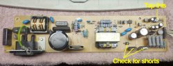
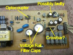
Found on a website, someone said they had the same problem as me..said the high pitched whining was coming from what he thought was a 400v 82uf cap near the power socket...could this be the problem?

Another guess from my dad who used to service TV's and VCR's is that the switching power supply went out...If so, is it safe to say this thing is trash?
 
Last edited:
Switch Mode Power Supplies are generally easily fixed.

If it's squealing like that, something is probably placing an excessive load on the output. This could be something external to the PSU or the rectifier diodes or caps on the output of the PSU, or even a small electrolytic cap in the pulse width modulator circuit. If your dad fixed TVs, he'll already know these. ;)

BTW, hopefully, when you stored it away, you stored it upright. These printers (made by Canon for Apple) have a large waste ink pad in the base of the unit. Sometimes if stored on-end or any other way than upright, the ink can leak out onto the electronics.

You can use an equivalent Canon printer power supply from a Canon BJC4000

You could try removing the print head (lift the blue lever up to dis-engage), since there is a heater in the head.

You could also disconnect the two motors one at a time to see if that at least allows the power supply to power up.

The Apple service part number for a 110v PSU is 661-0162 (of course no longer available)

The Canon 110V PSU part is QH3-3158-000 (most likely on a label on the back of the power supply assembly.

You may find the PDF (look at the right hand column) here VERY handy.

http://archive.org/details/printermanual-apple-color-stylewriter-2400-service-source

DO be careful of plastic clips when dis-assembling. Given it's age, some case plastics may be brittle.
 
Switch Mode Power Supplies are generally easily fixed.

If it's squealing like that, something is probably placing an excessive load on the output. This could be something external to the PSU or the rectifier diodes or caps on the output of the PSU, or even a small electrolytic cap in the pulse width modulator circuit. If your dad fixed TVs, he'll already know these. ;)
I asked him about it, and he said he rather not fix it because he has wasted too much time during his life fixing switching power supplies. However, that doesn't mean he can't fix it, he just isn't going to or help. >:/

I know for sure (I think) it is coming from the capacitor. If I have a capacitor that has a higher uF and voltage rating, should it fix it if everything else on the board is O.K.? I did store it upright...I left it in my massive band locker, and locked it, since nothing is being stored in it at this moment.

Also, I missed out on getting an Epson 800 on ebay that was in beautiful condition, and was within driving distance for pickup. :(
 
Update--
I tried replacing the the 200v 330uF cap with a 180v 820uF, and it still started whining. That cap was the only big one I had that was somewhat close to the ratings of the original. When I took the board off, I noticed some dark spots on the board right under the transformer(?).

Do you think it could have burned up? Is there somewhere where I can ask people about these kind of power supplies? I hate to get rid of it, but if it is cooked, then I will have to trash it.
http://i1177.photobucket.com/albums/x345/Foxx1996/2013-04-13_00-15-25_782_zps1badd46a.jpg
http://i1177.photobucket.com/albums/x345/Foxx1996/2013-04-13_00-15-12_428_zps341d8e01.jpg
 
Thats just extended exposure to heat. But nowhere near "burned up".

You might try re-soldering around there though, could be cold solder/cracks.
 
Update--
I tried replacing the the 200v 330uF cap with a 180v 820uF, and it still started whining. That cap was the only big one I had that was somewhat close to the ratings of the original. When I took the board off, I noticed some dark spots on the board right under the transformer(?).

Do you think it could have burned up? Is there somewhere where I can ask people about these kind of power supplies? I hate to get rid of it, but if it is cooked, then I will have to trash it.

Thats just extended exposure to heat. But nowhere near "burned up".

You might try re-soldering around there though, could be cold solder/cracks.

Yup, just hot running resistors slowly cooking the PCB. Nothing to be too alarmed about.

Did you try disconnecting the two motors?

Can you provide a good pic of the entire board? If so, I'll point out what to check/replace as an educated guess.
 
Did you try disconnecting the two motors?

Can you provide a good pic of the entire board? If so, I'll point out what to check/replace as an educated guess.

I did, I turned it on with all the wires to the logic board disconnected.

I have 3 pictures -- 1 of the entire board, then 1 of each side of the board (1 left, 1 right). If you need closer pictures of the parts, or numbers that are printed on the parts, let me know!

http://i1177.photobucket.com/albums/x345/Foxx1996/2013-04-14_22-38-29_294_zps6ec0fd48.jpg

http://i1177.photobucket.com/albums/x345/Foxx1996/2013-04-14_22-38-48_715_zps5cbb7cc2.jpg

http://i1177.photobucket.com/albums/x345/Foxx1996/2013-04-14_22-38-36_559_zpsb0a80d4a.jpg
 
Great pics! :)

WARNING: Switch Mode Power Supplies carry lethal voltages! Do not touch ANY exposed components whilst operating the power supply! Remount it in it's metal mounting before testing. Make sure the components mounted to the vertical metal part are secured with their brackets or they will over-heat and fail. Take careful note with the small metal cutout board guides when re-mounting the circuit board.

As a starting point, I'd be checking what appears to be the three rectifiers on the output for shorts. You may need to desolder them to check. In the attached pics I've marked which ones to check. The two "flat packs" that I've indicated should be considered as two diodes with one of the ends of each diode joined together into a "common".

The other one that strikes me since this appeared to fail suddenly from storage is the pesky little trimpot which I've marked as "Tap this". Put the PSU board back in and hook it up. Whilst pressing the power on button on the top of the logic board, tap the trimpot repeatedly with the plastic handle end of a small screw driver (or a suitable hard plastic tool). If you get intermittent cessation of the high pitched squeal, then you'll need to find a suitable 1K ohm top adjust trimpot. Adjusting the trimpot is not something I have a procedure for. A trick can be to measure the old one but will depend on how it's wired in circuit. Sometimes two legs are shorted together, sometimes not.

Take a pic of the solder side of the board where the trimpot is mounted.

Also, just for reference, a pic showing the part numbers on the front of the two "flat packs" I've indicated.

I've sometimes spent days chasing a fault in a SMPS, only to find one of the pesky trimpots faulty. The Apple 14" Color Display being a case in point. Ended up being VERY comon.
 

Attachments

  • PSU HINT annot crop.jpg
    PSU HINT annot crop.jpg
    172.4 KB · Views: 147
Last edited:
Ok, since it might be annoying for me to quote a lot of what you wrote, I will try to respond in order of your explanation goes.

The three things you pointed out, one of them is a voltage regulator, one is a rectifier, and I don't know what the 2 pin diode is. I tested the trim-pot, and it checked out ok, with a max reading of ≈ 928Ω and a minimum of 0Ω. When I tested the voltage regulator, with the common side as the center, it did not read the same on each side when I moved the test lead to each of the legs. (One test lead in the middle, then move the other to each leg.) So, I found another voltage regulator of the same model and replaced it. No luck.

Do you still want a picture of where the trimpot is located? I noticed that when I heated that spot too much with the soldering iron, the copper traces started to "float" in a sense, and on one part it broke, so I had to add a wire there. So the lesson I learned is don't heat one spot for too long. :eek:

When I checked the three legged rectifier, it seemed ok, but I'm not sure what the normal values are for it. The symbol for it looks similar to this:

->|<-

Could it be either of the two rectifiers? I know the voltage regulator is fine because it came off a working TV board that I took when we scrapped our old TV. I did notice when the trim pot is close to 0, it takes longer for the whining to start, but not by much, as opposed to when it is close to 500Ω, it whines as soon as I plug it in. I did get the lights to turn on, and the motors to move for 2 seconds, but then it started whining.

Also, do you need any other pictures?
 
When I checked the three legged rectifier, it seemed ok, but I'm not sure what the normal values are for it. The symbol for it looks similar to this:

->|<-
The center pin is common and each outer pins are the anode of each diode. You should get a high resistance (infinite resistance) in one direction/polarity, and a lower resistance in the other polarity of each diode. You may need to use a multimeter that has a diode check function.

Could it be either of the two rectifiers? I know the voltage regulator is fine because it came off a working TV board that I took when we scrapped our old TV. I did notice when the trim pot is close to 0, it takes longer for the whining to start, but not by much, as opposed to when it is close to 500Ω, it whines as soon as I plug it in.

I did get the lights to turn on, and the motors to move for 2 seconds, but then it started whining.

These are interesting observations that would seem to indicate that there isn't a 'hard failure' of a semiconductor component in the power supply. Rather, there is a slightly higher load than the power supply is designed to deliver. The causes here can be the capacitors on the output of the power supply, or a bad capacitor associated with the pulse width modulator circuit (which the trimpot allows fine adjustment fed back thru the opto-coupler).

Of course, the output filter caps could also be faulty, as could the other 3 un-identified smaller caps that are bundled together.

One thing to check might be freedom of movement of the motors. If the bearings are a little seized, that might also make the difference.

Do you have pics of the two 'flat pack' components? Just for curiosity.

And yes, a pic of the FULL bottom of the PCB (particularly the output half). I've a hunch that the capacitor next to the trimpot could be faulty, but I'm not sure what the other smaller caps are associated with. The other 'flatpack' with the tall thin heatsink in the center of the board near the output is probably some kind of crow-bar circuit.
 

Attachments

  • Output annot crop.jpg
    Output annot crop.jpg
    75 KB · Views: 128
Last edited:
The center pin is common and each outer pins are the anode of each diode. You should get a high resistance (infinite resistance) in one direction/polarity, and a lower resistance in the other polarity of each diode. You may need to use a multimeter that has a diode check function.

Of course, the output filter caps could also be faulty, as could the other 3 un-identified smaller caps that are bundled together.

One thing to check might be freedom of movement of the motors. If the bearings are a little seized, that might also make the difference.

I don't think they are seized since they have moved before, but I guess it doesn't hurt to look! I think I will replace that cap that you think is faulty, which is right next to the pot. (That is if I have one rated for 50v, .47uF)

Do you have pics of the two 'flat pack' components? Just for curiosity.
Here ya go!
http://i1177.photobucket.com/albums/x345/Foxx1996/2013-04-16_23-02-28_381_zpseec63e0f.jpg
Like I said, I heated that one spot for too long, and the trace broke. I did put the wire on it before I powered it on.

And yes, a pic of the FULL bottom of the PCB (particularly the output half). I've a hunch that the capacitor next to the trimpot could be faulty, but I'm not sure what the other smaller caps are associated with.
http://i1177.photobucket.com/albums/x345/Foxx1996/2013-04-16_23-01-24_438_zpsdb8ee5ac.jpg

Also, I noticed on the board--if you look at the underside picture, if you look to at the middle, then go directly left just a bit, there are two pins, and a weird looking dark spot. I noticed on the board that there are dark blotches there...Is it safe to assume that is normal?
 
Also, I noticed on the board--if you look at the underside picture, if you look to at the middle, then go directly left just a bit, there are two pins, and a weird looking dark spot. I noticed on the board that there are dark blotches there...Is it safe to assume that is normal?

BINGO! No.. that is a pretty good sign that the capacitor soldered there is leaking and has been corroding the tracks underneath the lacquer.

Remove that capacitor (mind the fishy smell) and then carefully scrape that area of track gently back to bare copper. Cover the area in solder and put in a new capacitor to replace C102.

You may have to experiment a little with cleaning the track. If it is etched thru, you can replace it with solder braid or completely stripped twisted wire bridge. The point is to get rid of any copper track that is corroded. Clean both sides of the board with alcohol or other cleaner to remove the leaked electrolyte.

:) I'm betting this will fix it.
 
BINGO! No.. that is a pretty good sign that the capacitor soldered there is leaking and has been corroding the tracks underneath the lacquer.

Remove that capacitor (mind the fishy smell) and then carefully scrape that area of track gently back to bare copper. Cover the area in solder and put in a new capacitor to replace C102.

You were correct! The capacitor had leaked out and down the positive terminal, and I replaced the old 16v 470uf with a 25v 470uf I had laying around. I know I should clean the traces, but I took an ohm reading and from each lead that was affected to another good lead, and everything seemed to check out ok. Put everything back together, plugged in aaannnddd.....nothing. Just the usual whining. So I put the original voltage regulator and main cap back on, still nothing.

Could the affected traces, even though they were fine on the ohm meter, still be causing this problem? If so, I am going to wait to have my dad help me clean it because he has had experience doing it, and I don't want to eff anything else up. Do you think the bad cap when it went out could have damaged anything else on the board?

Grab an identical 16v cap from somewhere, you can't swap out caps with different voltages. Also, make sure you clean the pads, the electrolyte will corrode the metal, shorts aren't necessarily the only concern in this case.
 
Yup. You really MUST to clean the pcb (top and bottom) before you replace the capacitor.

Yes, a capacitor in that state CAN do damage to other components, both by stressing the circuit (though that IS rare), but also by corroding the pins of other components nearby. Have a good look at nearby component legs (on the component side) for any signs of corrosion.

You may end up having to replace all the capacitors on the output stage. Both the large caps, the one next to the trimpot, and the 3 small ones.

That particular capacitor filters the feed to the 7805 flatpack (TO-220) regulator.

If you use the RJ09 link as positive, and the pin on the outside edge of R115, this should give you the DC in to the 7805, which should be IIRC at least 7 volts or higher.
 
My dad checked everything on the board, and no luck. He thinks, and I agree with him, that the transformer may have overheated at some point and caused some of the windings to short out, changing the transformer's properties and how it oscillates (or something like that). I only payed 5 bucks for the thing, so I wouldn't really be loosing much money if I threw it out. I may keep the front piece with the badge, and logic board, but the rest is going to be thrown out :(
 
Register on MacRumors! This sidebar will go away, and you'll see fewer ads.