Got a tip for us?
Let us know
Become a MacRumors Supporter for $50/year with no ads, ability to filter front page stories, and private forums.
HELP: What is this added wire and components?
- Thread starter sirchopper
- Start date
- Sort by reaction score
You are using an out of date browser. It may not display this or other websites correctly.
You should upgrade or use an alternative browser.
You should upgrade or use an alternative browser.
Picture sucks too much to answer question. Please get rid of paint line drawing and show where it goes to.
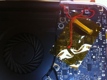
Just taken this photo. I bought the mac second hand so i guess it has had some kind of LCD issue in the past and this is the fix, as it follows the main LCD cable and is soldered to one of the other components on the logic board??? Not sure what the logic board component is though? Any ideas???
Attachments
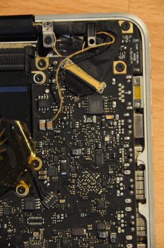
Significant differences than the MBP in this image from iFixit. You could be right that it's some kind of fix. Perhaps it's a nefarious add-on.
Cheers guys. So would you think that if I replaced the screen with a correct version (if it is the case that the current screen is the incorrect one), then I wouldn't need the extra wire???
Looks like a fairly normal repair job, very unlikely to be nefarious in any way. Although this repair would be something the previous owner should have mentioned to you.
Could be that the LCD connector or cable are damaged, and were bypassed by splicing those wires from the display cable and soldering them to that capacitor.
If the connector on the logic board is damaged, switching the display assembly won't do any good. You'd have to do something similar with the new display too.
Looks like a fairly normal repair job, very unlikely to be nefarious in any way. Although this repair would be something the previous owner should have mentioned to you.
Could be that the LCD connector or cable are damaged, and were bypassed by splicing those wires from the display cable and soldering them to that capacitor.
If the connector on the logic board is damaged, switching the display assembly won't do any good. You'd have to do something similar with the new display too.
Thanks laurihoefs, the previous owner only had it for three years so it must have happened before this. Does this seem like a simple solder as I want to remove the screen from the base to replace the screen rubber seal, but initially i didn't want to mess with the extra soldered wire.....?
Soldering thin wires to a small pad can be a bit tricky, so you might want to find someone with a bit of experience to do it for you. And you might also want to find out why the repair was done in the first place.Thanks laurihoefs, the previous owner only had it for three years so it must have happened before this. Does this seem like a simple solder as I want to remove the screen from the base to replace the screen rubber seal, but initially i didn't want to mess with the extra soldered wire.....?
IMHO, the repair most likely has something to do with the LCD backlight. Does the backlight brightness adjust normally? If everything works, then the easiest and cheapest solution is to desolder the wires, replace the seal, and then solder them back.
EDIT: If all you want to replace is the rubber seal, then you should be able to do that without removing the screen.
Last edited:
Soldering thin wires to a small pad can be a bit tricky, so you might want to find someone with a bit of experience to do it for you. And you might also want to find out why the repair was done in the first place.
IMHO, the repair most likely has something to do with the LCD backlight. Does the backlight brightness adjust normally? If everything works, then the easiest and cheapest solution is to desolder the wires, replace the seal, and then solder them back.
EDIT: If all you want to replace is the rubber seal, then you should be able to do that without removing the screen.
Everything works absolutely fine and backlight works as expected, but I can see that the glass has been removed and the rubber is deformed, probably due to a heat gun around the edge of the screen to remove it, and tiny marks under the glass. I would prefer to make it look crisp again
")
All tuts that I have read start with removing the screen from the base, otherwise the space might be too tight to get to the bottom of the seal...
Everything works absolutely fine and backlight works as expected, but I can see that the glass has been removed and the rubber is deformed, probably due to a heat gun around the edge of the screen to remove it, and tiny marks under the glass. I would prefer to make it look crisp again
All tuts that I have read start with removing the screen from the base, otherwise the space might be too tight to get to the bottom of the seal...
Working with the display attached won't be easy, and you'll absolutely have to detach it if you are also planning on removing the glass.
If you don't have a small soldering iron and still want to start working on the display, you could just cut the wire near where it's soldered. The wire seems to easily be long enough, so it does not matter if you lose a tiny bit of length doing this.
Thanks! I do have a soldering iron and the wire is way long enough. I also thought about cutting it and adding a molex connector so it can slot into the cavity by the LCD connector. Waiting for replacement rubber seal to arrive and will let you know what I find when removing the screen.....Working with the display attached won't be easy, and you'll absolutely have to detach it if you are also planning on removing the glass.
If you don't have a small soldering iron and still want to start working on the display, you could just cut the wire near where it's soldered. The wire seems to easily be long enough, so it does not matter if you lose a tiny bit of length doing this.
Ha!! Life as we know it..... Seriously, i wouldn't want to short anything by doing that.It would also be interesting to know what stops working when you cut the wire.
Seems I was wrong about it having something to do with the backlight. I thought the large caps might have been smoothing caps for the backlight.
I don't have a 17" MBP at hand, but I measured the voltage at the two large caps near the LCD connector on my old rMBP. It's 3.3V, and I can't think of anything else in the display assembly that would require that voltage, than the panel.
I don't have a 17" MBP at hand, but I measured the voltage at the two large caps near the LCD connector on my old rMBP. It's 3.3V, and I can't think of anything else in the display assembly that would require that voltage, than the panel.
Interesting... So would you suspect that it's not the correct panel for the machine? Once i take it apart when the replacement rubber seal arrives, I will take some pictures if I can see where that little wire goes. I've not seen any other photos on the web with the same fix?Seems I was wrong about it having something to do with the backlight. I thought the large caps might have been smoothing caps for the backlight.
I don't have a 17" MBP at hand, but I measured the voltage at the two large caps near the LCD connector on my old rMBP. It's 3.3V, and I can't think of anything else in the display assembly that would require that voltage, than the panel.
I still think the most likely culprit is the connector on the logic board, or damage to any components or traces between the connector and those capacitors. But if there is no visible damage around the connector, it's hard to say.Interesting... So would you suspect that it's not the correct panel for the machine? Once i take it apart when the replacement rubber seal arrives, I will take some pictures if I can see where that little wire goes. I've not seen any other photos on the web with the same fix?
HOWEVER: A different panel is a possibility too. I quickly glanced over the datasheets of some LG 17" panels. I think the correct panel for your MPB is LP171WU6-TLA1? Interestingly, at least LP171WU6-TLA2 and LP171WU4-TLA1 have the same signalling and pinouts for data, but require at least one additional 3.3V wire.
So if those wires go to pins 2 and 3, and the panel model printed on the back is LP171WU6-(TL)(A1), then either the cable, or the logic board are damaged, and those wires are meant to bypass the damaged parts.
However, if the panel was replaced with LP171WU4, there would be at least one extra 3.3V wire in pin 5.
Last edited:
Wow. Pretty in-depth answer, thanks a lot!!!!! I will be taking it apart in a few weeks so will update you on what I find, but I will certainly keep all of this in mind. Thanks for your time so far and to the others who answered.I still think the most likely culprit is the connector on the logic board, or damage to any components or traces between the connector and those capacitors. But if there is no visible damage around the connector, it's hard to say.
HOWEVER: A different panel is a possibility too. I quickly glanced over the datasheets of some LG 17" panels. I think the correct panel for your MPB is LP171WU6-TLA1? Interestingly, at least LP171WU6-TLA2 and LP171WU4-TLA1 have the same signalling and pinouts for data, but require at least one additional 3.3V wire.
So if those wires go to pins 2 and 3, and the panel model printed on the back is LP171WU6-(TL)(A1), then either the cable, or the logic board are damaged, and those wires are meant to bypass the damaged parts.
However, if the panel was replaced with LP171WU4, there would be at least one extra 3.3V wire in pin 5.
Register on MacRumors! This sidebar will go away, and you'll see fewer ads.