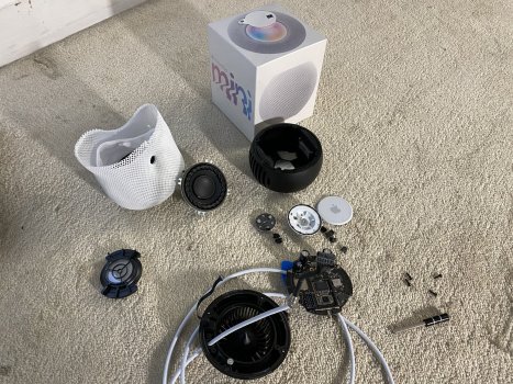
Quick note: I’m not sure where iFixit is with their teardown. They’ve been late with a lot of things this year. I’m still waiting for the iPad Air Teardown and Apple silicon Macs. I had to drive to another Apple Store to get my pair since I missed the preorder time and the local one didn't offer in store pickup. Just like with the first HomePod, I had to tear this one apart. I’ve only had my pair for 5 hours. The sound is great for it’s size just like with the original HomePod. It sounds bigger than it is, but as they say, "there’s no replacement for displacement". Same principle applies here. Just a small woofer and two passive radiators. No tweeters, etc. Also, the power cord is NOT replaceable DO NOT pull as it won’t come out (unlike the original HomePod) I was hoping to find a female lightning connector to help explain the leaked braided lightning to USB-C cable we saw over the summer. My 2 HomePod Mini units were Assembled in Vietnam. I'm not sure if that means these were manufactured by GoerTek (they make AirPods in Vietnam), Foxconn or Luxshare Precision.
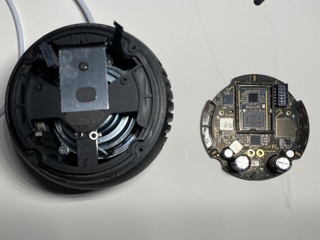
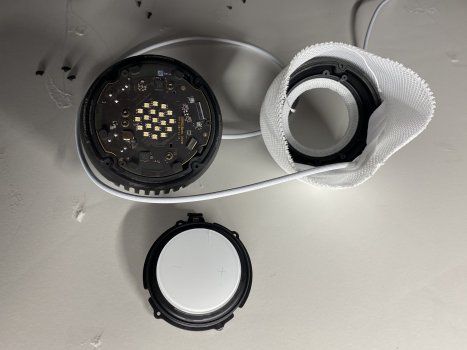
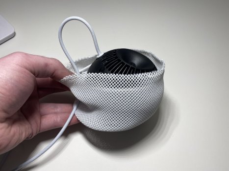
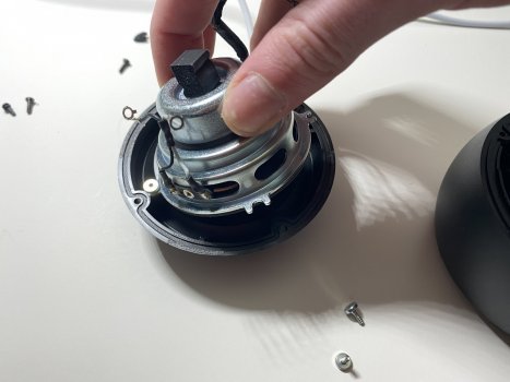
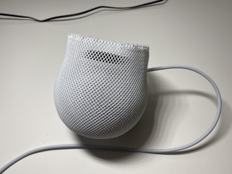
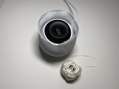
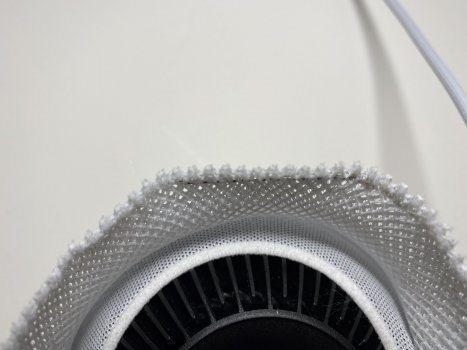
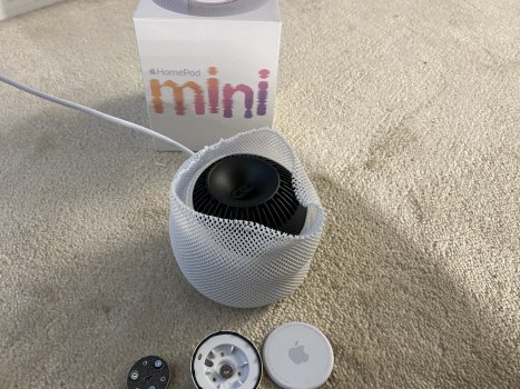
Let’s get to the fun part. The disassembly procedure is a bit different, and you need to be careful since the mesh doesn’t have long draw strings. You still open the HomePod Mini from the top, but you have to get in to the mesh first from the bottom. Do not try to remove the top plastic touch surface like in the original HomePod. Removing this is a great way to break it and isn't necessary for disassembly. Begin by removing the rubber circle, and then 3 T6 screws to remove a plastic disc plate. Then remove the bottom base T10 screw. Open up the mesh (there are tiny draw strings to be mindful of.. I will have to rethread mine) and pop the plastic grommet from around the power cord inlet.
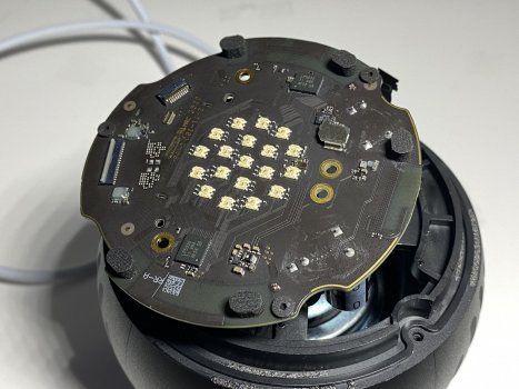
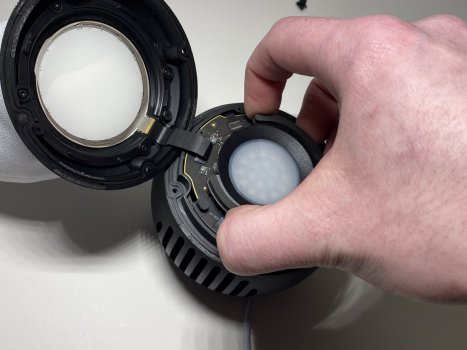
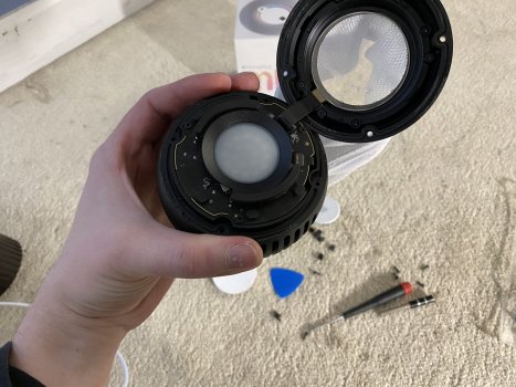
Remove the 4 rubber screw covers on the top side, remove the 4 T6 screws. Carefully separate the top from the HomePod Mini. Some moderate strength adhesive is used. Flip up the retaining tab and disconnect the digitizer ribbon cable. Flip up the retaining lever and remove the microphone ribbon cable. Pull off the LED diffuser, and remove 4 screws securing the logic board (two secure the logic board to the speaker ring terminals) Using a black stick, pry the logic board up and disconnect the power cable connector on the rear side (extremely difficult, so patience is required) Logic board comes out.
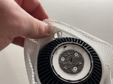
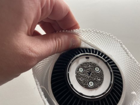
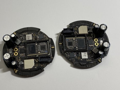
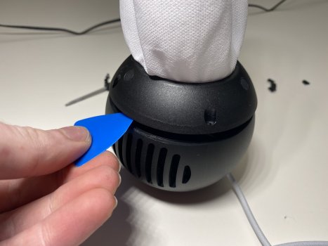
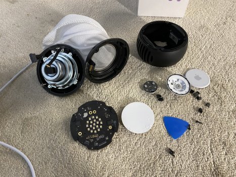
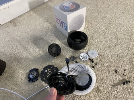
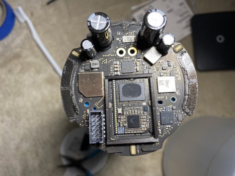
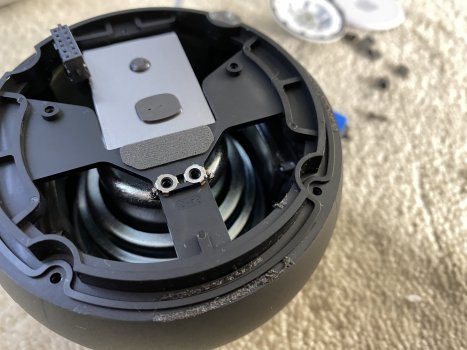
Using tweezers, CAREFULLY peel the microphone ribbon cable off of the sidewall. Lift out the speaker terminal rings. Now flip the HomePod Mini over and remove the 4 rubber screw covers on the bottom side, remove the 4 T6 screws. Bottom comes out (also held together with some moderate strength adhesive like the top half). You can remove the speaker driver by removing the 4 T6 screws (or removing 2, and loosening the other 2) Most of the markings on the NAND flash storage IC aren't readable as some of the markings on the processor
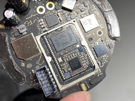
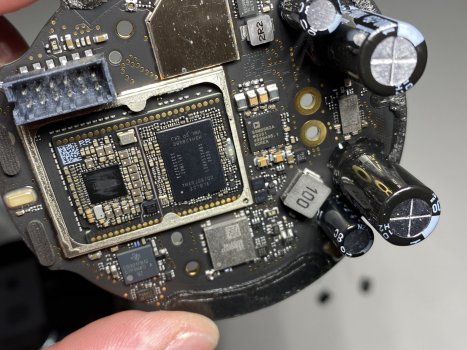
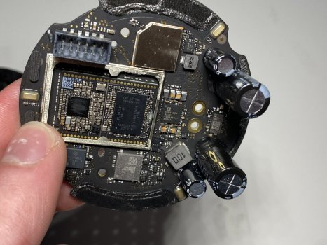
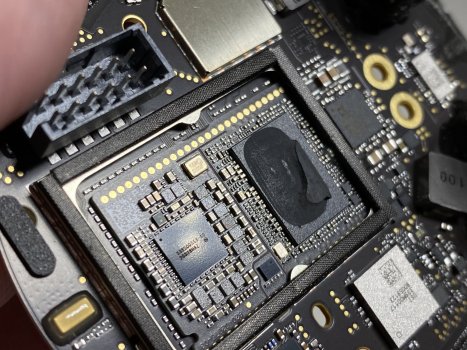
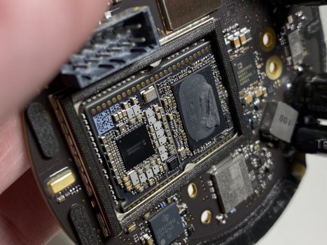
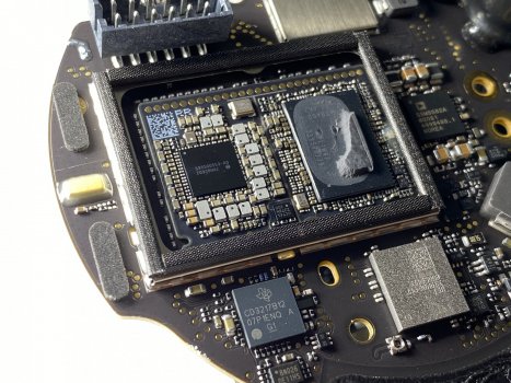
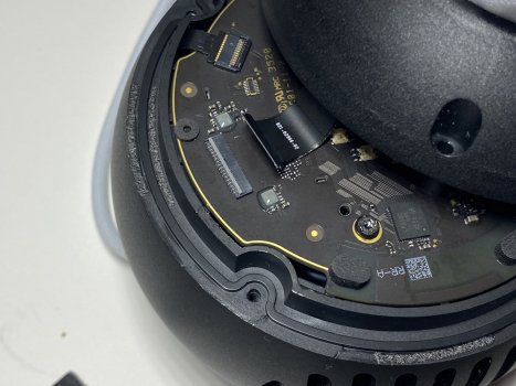
The S5 (System in Package a.k.a SiP) appears to be on it's own daughter PCB which is then soldered to the main PCB (photo 6) The NAND flash storage is the larger IC and the processor is the smaller IC. Most of the markings on the NAND flash storage IC aren't readable as some of the markings on the processor
Sorry for the incomplete, quick and dirty right up. Have to catch some rest, work in 6 hours.
Let’s get to the fun part. The disassembly procedure is a bit different, and you need to be careful since the mesh doesn’t have long draw strings. You still open the HomePod Mini from the top, but you have to get in to the mesh first from the bottom. Do not try to remove the top plastic touch surface like in the original HomePod. Removing this is a great way to break it and isn't necessary for disassembly. Begin by removing the rubber circle, and then 3 T6 screws to remove a plastic disc plate. Then remove the bottom base T10 screw. Open up the mesh (there are tiny draw strings to be mindful of.. I will have to rethread mine) and pop the plastic grommet from around the power cord inlet.
Remove the 4 rubber screw covers on the top side, remove the 4 T6 screws. Carefully separate the top from the HomePod Mini. Some moderate strength adhesive is used. Flip up the retaining tab and disconnect the digitizer ribbon cable. Flip up the retaining lever and remove the microphone ribbon cable. Pull off the LED diffuser, and remove 4 screws securing the logic board (two secure the logic board to the speaker ring terminals) Using a black stick, pry the logic board up and disconnect the power cable connector on the rear side (extremely difficult, so patience is required) Logic board comes out.
Using tweezers, CAREFULLY peel the microphone ribbon cable off of the sidewall. Lift out the speaker terminal rings. Now flip the HomePod Mini over and remove the 4 rubber screw covers on the bottom side, remove the 4 T6 screws. Bottom comes out (also held together with some moderate strength adhesive like the top half). You can remove the speaker driver by removing the 4 T6 screws (or removing 2, and loosening the other 2) Most of the markings on the NAND flash storage IC aren't readable as some of the markings on the processor
The S5 (System in Package a.k.a SiP) appears to be on it's own daughter PCB which is then soldered to the main PCB (photo 6) The NAND flash storage is the larger IC and the processor is the smaller IC. Most of the markings on the NAND flash storage IC aren't readable as some of the markings on the processor
Sorry for the incomplete, quick and dirty right up. Have to catch some rest, work in 6 hours.
Attachments
-
 8529E46C-B311-4C6F-9799-749773591EF6.jpeg639 KB · Views: 5,751
 -
 0DCED0FF-8402-4FFE-B916-E55CCD800B9B.jpeg455.3 KB · Views: 2,643
 -
 0E9A26B3-6D03-4AC9-8F34-F6DE5BCF6C2F.jpeg871.5 KB · Views: 2,889
 -
 3528D428-78E8-4A88-91F5-0072911BF12F.jpeg895.3 KB · Views: 2,734
 -
 766CA451-8CCB-4FC5-9BBD-C02C379C808D.jpeg1,014.2 KB · Views: 2,640
 -
 2CE5000D-2AB9-47C2-AF1C-B8C74B6E4C93.jpeg481 KB · Views: 2,712
 -
 CDD3619D-B8BB-4B65-9BE1-E14E77C6B363.jpeg418.2 KB · Views: 2,541
 -
 9DD06122-D60D-4BB0-989D-618EBEA60DA4.jpeg370.5 KB · Views: 2,363
Last edited: