A thread to chronicle my journey of creating a modern iBook. This has been a long series of trials and tribulations as it is far beyond anything I have done before with electronics.
I'll add in more detail and photos of course but this is my opening salvo partly to record everything and partly to vent/be amazed at Apple's engineering integration.
This all started from my wife telling me how much she loves the clamshell orange iBook and me stupidly saying I could make her a modern one for her birthday - this was in Feb 21 for her March birthday...
So I started by trying to get a cheap G3 - not easy at all. Ended up with 3, 2 Tangerine and one Blueberry - and none of them were cheap but I had an idea I would probably need more than one if any bits broke. I also bought a bunch of stuff I knew I would need, a soldering station, Dremel, attachments for both, screw organising boxes and various other ancillaries.
What I thought the hardest part would be is the display (I was wrong with hindsight). I spent a long time researching the biggest modern display I could get to fit in the display casing and ended up with a LQ125D1JW34 from Aliexpress.
The display came with a controller board and I could never get it to work. The seller was useless and despite saying it could be powered by USB, it couldn't! I had taken one unit completely apart by this point and made rough estimates on how I could integrate a logic board/battery/etc.
I tried to get a matching connector for the keyboard but found it near impossible and was even considering cannibalising the G3 LB just for the connector but that seemed an extreme waste. Had a go at working out the trackpad but couldn't find a pinout for it so gave up on that.
I pretty much lost interest at this point with the display not working and the seller being completely unhelpful so had a 9 month lull - and work was really busy too.
Anyway back to just after new year this year and I was reinvigorated in the project to again try and get it done as a birthday present (wrong again!).
Key bits were firstly to sort the display out, so I bought 2 new controller boards and one display/controller board package. The point being I could then cross test between parts to work out what did and didn't work. The combined package turned up without a controller board, but luckily one of the controller boards did work, and both displays do function - finally some good news on the project.
As I finally had a working display - I thought I should get that bit as complete as possible. The display is widescreen and wider but shorter than the G3 one - so I bought some screen printed display glass to cover the gaps from Alibaba. Turned up, no issues at all. Got my Dremel out finally and set to work cutting the hole for the display. I felt bad cutting into such a design icon but for a modern laptop I don't think 4:3 works; plus I couldn't find a 4:3 display of the right size with decent resolution. The cutting went pretty well, its not perfect but I can smooth it out later. The glass is perfect and I put together a new G3 display case with a 4K display in it!
Now I started thinking much more about the electrical elements:
I wasn't that keen on using the 2019 MBP because it only has 2 TB ports and it was not an M1. I (drunkenly) bought a smashed screen M1 Air and 2018 MBA. The latter might seem worse than the MBP, but it is fanless which I saw as a benefit.
This is where I found out that there are undocumented (as far as I can tell) differences between various MacBooks. The two MBAs cannot power the display controller when on battery power - but as soon as you plug in a charger it comes on instantly. Seems absolutely crazy and I could probably do some further debugging on it to see if its just my display or if it will fast charge an iPhone over USB-C either way (note to self). My daily driver 2018 4TB MBP has no issues driving it at all.
With the power issues I went back to the 2019 MBP as a compromise. However in trying to remove the battery it set on fire. I read all the fixit warnings and I knew the risks but it split and went up in flames. luckily the LB and other key bits had all been removed prior. I bought a new battery but couldn't get it to power up, ended up selling it for parts on eBay and the new guy got it working so kudos to him.
The MBAs not working natively was annoying because they have a tiny logic board. So I decided I could run the MB from an external battery integrated inside - which would not only improve battery life but also allow the small logic board. Then I found out that power banks with have dual PD outputs are very expensive. I bought the cheapest one I could find at £80 but it is very chunky. So I had all but changed my mind on this route - but still decided to disassemble the battery pack, breaking the circuit in the process and so no refund for me (doh). you may wonder why I didn't just get a little battery pack for the screen considering its very low power use, and the answer is I wanted it to be 'native' - I didn't want my wife to have to know she had to charge two separate batteries.
By this point I knew I had to get a MBP again, and decided it had to be a 4TB one for the flexibility on ports. Turns out that people selling damaged 4TB models are incredibly rare on eBay UK. There are loads of M1s, MBAs, 2TB models but very few 4TB ones. And most of the ones that do are LB or water damaged and I basically needed a display damaged one. Eventually I just took a punt on one which someone said chimed but seemed had no display output internal or external. It turned up and after a while messing about with it (swapped LB into my working MBP to check it wasn't a failed display) I ended up DFU restoring it and still nada. This was pretty annoying. But as luck would have it, I reassembled it all, plugged it in and voila, booting like normal no issues. Internet recovery kept screwing up but eventually fixed that and now I have a fully working donor laptop.
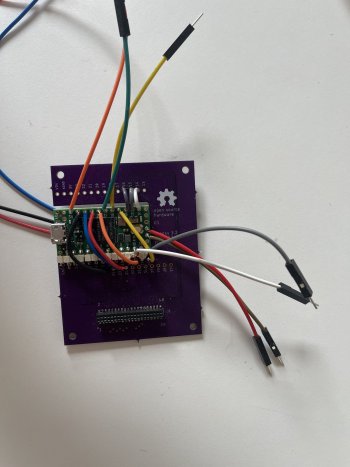
In parallel with all of this on points 4 and 5, I had been working out how to get the keyboard and trackpad working. As my luck would have it, in my hiatus, someone had actually worked out the right connector and pinout for the keyboard and how to interface it to a teensy. https://www.instructables.com/How-to-Make-a-USB-Laptop-Keyboard-Controller/ So I bought the connectors (at huge cost!), got a board printed (huge cost again) and waited for it to arrive. The bits came, and I set about soldering. I dont know where I went wrong but something was off with some of the connectors and despite trying to trace the fault or short with my multimeter I had no luck so the keyboard was put on hold.
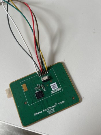
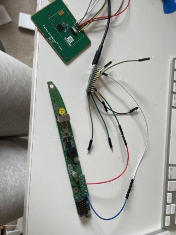
As I mentioned earlier, the trackpad seemed a dead end. By a little bit of luck, I was looking for an alternate trackpad and while doing so found a guide where someone had created a USB touchpad from the exact part I was looking at. Its a direct size replacement for the iBook one so is perfect. It runs on the I2C protocol so again interfaces nicely via a teensy. I soldered on my wires, loaded the code and voila, working touchpad. The second working bit of my iBook after more than a year. The one annoying thing was the code for tap to click was very basic in its implementation due to limitations from being forced to act as a mouse - and it was sort of unusable so I needed a solution. I bought some tiny pushbuttons but after they arrived I realised I could just use the original iBook button circuit board - which is separate from the touchpad. I worked out the pinout, soldered on my jumper wires, modified my teensy code and again voila, working easy trackpad button.
Back to the keyboard, I was annoyed but as I had bought extra connectors originally, I bought some additional PCBs. spent a lot of time and care soldering this time. Loaded the amended code for my specific wiring arrangement and finally all working - part number 3 working.
Around this time I also bought some USB hubs to firstly give me the required HDMI for the display controller (MacBooks don't do HDMI over USB C) and USB internally for my teensy, and secondly give me some external non-USB-C ports as an added bonus. I also researched and found that old FaceTime HD cameras from MacBook Pros work on USB and so can be free-wired!. One from a 2012 model arrived today and considering they were 720P for 10 years until the M1 models arrived, it can't be bad at all once I get it wired.
Now the focus switched to the board itself and thats where I am now. The first problem I realised was the power button. Its a physical button on the bottom of the Touch ID button and as far as I can tell there is no other way to power up a MBP. And if you didn't know, the Touch ID button cable is only about 1cm long and its very thin and fragile. I was trying to work out a way to use the original power button to push down on the Touch ID button mounted invisibly internally but its placement and my big logic board meant it was just not going to work. So I decided its unfortunately time to cut the case again and I'll have a real working Touch ID button. No huge deal, marked the house using the mounting bracket, drilled, cut the cable hole and mounted it - as I had just drilled holes through the case, the top of the buttons was probably about 3mm proud. connected the logic board it was tight it was never going to work. So onto plan B, cut a full square hole for the button and mount it flush with a bracket supporting from below and that gives me a couple of mm of cable to play with. Got that finished today and test fit the LB. its very tight but just about workable if I leave a little play in the LB mounting to allow the cable to flex.
Now we are at today and I thought I was at the finishing stretch - time to completely strip the donor to start a detailed test fit for the iBook. Got the isopropyl out and safely this time removed the battery. speakers etc all removed. And this was when I nearly fell off my chair because it's when I found out the fans are not connected by the two connector cables which are right next to the fans as you remove the logic board. Oh no, they are connected directly to the keyboard! And looking at the board schematics, its not even piggybacked off the connector and hardwired - where I may by some miracle have been able to free wire them. No, the connector is marked as an SOC debug connector with various USB lines running through it - so again I am at a brick wall.
I have nearly run out of energy with the project so I thought I will just remove the keyboard and mount it internally and that will allow it to run the fans. So I set about removing the about 50 tiny P2 screws holding it in place, only to have it still not budging. Because its riveted in place! This is where I hark back to my second Lin, I don't know whether to applaud or castigate apple for their work.
I'll have a think, but I'm considering reshaping the aluminium bottom case so it will fit in the iBook shell, but then I am again back to no Touch ID solution so thats a no-go.
I hope my thread has been slightly entertaining for you reading about my trials and tribulations, I will update with further photos, links, part numbers and credit to relevant contributors when I get a chance.
I'll add in more detail and photos of course but this is my opening salvo partly to record everything and partly to vent/be amazed at Apple's engineering integration.
This all started from my wife telling me how much she loves the clamshell orange iBook and me stupidly saying I could make her a modern one for her birthday - this was in Feb 21 for her March birthday...
So I started by trying to get a cheap G3 - not easy at all. Ended up with 3, 2 Tangerine and one Blueberry - and none of them were cheap but I had an idea I would probably need more than one if any bits broke. I also bought a bunch of stuff I knew I would need, a soldering station, Dremel, attachments for both, screw organising boxes and various other ancillaries.
What I thought the hardest part would be is the display (I was wrong with hindsight). I spent a long time researching the biggest modern display I could get to fit in the display casing and ended up with a LQ125D1JW34 from Aliexpress.
The display came with a controller board and I could never get it to work. The seller was useless and despite saying it could be powered by USB, it couldn't! I had taken one unit completely apart by this point and made rough estimates on how I could integrate a logic board/battery/etc.
I tried to get a matching connector for the keyboard but found it near impossible and was even considering cannibalising the G3 LB just for the connector but that seemed an extreme waste. Had a go at working out the trackpad but couldn't find a pinout for it so gave up on that.
I pretty much lost interest at this point with the display not working and the seller being completely unhelpful so had a 9 month lull - and work was really busy too.
Anyway back to just after new year this year and I was reinvigorated in the project to again try and get it done as a birthday present (wrong again!).
Key bits were firstly to sort the display out, so I bought 2 new controller boards and one display/controller board package. The point being I could then cross test between parts to work out what did and didn't work. The combined package turned up without a controller board, but luckily one of the controller boards did work, and both displays do function - finally some good news on the project.
As I finally had a working display - I thought I should get that bit as complete as possible. The display is widescreen and wider but shorter than the G3 one - so I bought some screen printed display glass to cover the gaps from Alibaba. Turned up, no issues at all. Got my Dremel out finally and set to work cutting the hole for the display. I felt bad cutting into such a design icon but for a modern laptop I don't think 4:3 works; plus I couldn't find a 4:3 display of the right size with decent resolution. The cutting went pretty well, its not perfect but I can smooth it out later. The glass is perfect and I put together a new G3 display case with a 4K display in it!
Now I started thinking much more about the electrical elements:
- Keyboard
- Trackpad
- Ports
- Display controller integration
- Which laptop to use as a donor
I wasn't that keen on using the 2019 MBP because it only has 2 TB ports and it was not an M1. I (drunkenly) bought a smashed screen M1 Air and 2018 MBA. The latter might seem worse than the MBP, but it is fanless which I saw as a benefit.
This is where I found out that there are undocumented (as far as I can tell) differences between various MacBooks. The two MBAs cannot power the display controller when on battery power - but as soon as you plug in a charger it comes on instantly. Seems absolutely crazy and I could probably do some further debugging on it to see if its just my display or if it will fast charge an iPhone over USB-C either way (note to self). My daily driver 2018 4TB MBP has no issues driving it at all.
With the power issues I went back to the 2019 MBP as a compromise. However in trying to remove the battery it set on fire. I read all the fixit warnings and I knew the risks but it split and went up in flames. luckily the LB and other key bits had all been removed prior. I bought a new battery but couldn't get it to power up, ended up selling it for parts on eBay and the new guy got it working so kudos to him.
The MBAs not working natively was annoying because they have a tiny logic board. So I decided I could run the MB from an external battery integrated inside - which would not only improve battery life but also allow the small logic board. Then I found out that power banks with have dual PD outputs are very expensive. I bought the cheapest one I could find at £80 but it is very chunky. So I had all but changed my mind on this route - but still decided to disassemble the battery pack, breaking the circuit in the process and so no refund for me (doh). you may wonder why I didn't just get a little battery pack for the screen considering its very low power use, and the answer is I wanted it to be 'native' - I didn't want my wife to have to know she had to charge two separate batteries.
By this point I knew I had to get a MBP again, and decided it had to be a 4TB one for the flexibility on ports. Turns out that people selling damaged 4TB models are incredibly rare on eBay UK. There are loads of M1s, MBAs, 2TB models but very few 4TB ones. And most of the ones that do are LB or water damaged and I basically needed a display damaged one. Eventually I just took a punt on one which someone said chimed but seemed had no display output internal or external. It turned up and after a while messing about with it (swapped LB into my working MBP to check it wasn't a failed display) I ended up DFU restoring it and still nada. This was pretty annoying. But as luck would have it, I reassembled it all, plugged it in and voila, booting like normal no issues. Internet recovery kept screwing up but eventually fixed that and now I have a fully working donor laptop.
In parallel with all of this on points 4 and 5, I had been working out how to get the keyboard and trackpad working. As my luck would have it, in my hiatus, someone had actually worked out the right connector and pinout for the keyboard and how to interface it to a teensy. https://www.instructables.com/How-to-Make-a-USB-Laptop-Keyboard-Controller/ So I bought the connectors (at huge cost!), got a board printed (huge cost again) and waited for it to arrive. The bits came, and I set about soldering. I dont know where I went wrong but something was off with some of the connectors and despite trying to trace the fault or short with my multimeter I had no luck so the keyboard was put on hold.
As I mentioned earlier, the trackpad seemed a dead end. By a little bit of luck, I was looking for an alternate trackpad and while doing so found a guide where someone had created a USB touchpad from the exact part I was looking at. Its a direct size replacement for the iBook one so is perfect. It runs on the I2C protocol so again interfaces nicely via a teensy. I soldered on my wires, loaded the code and voila, working touchpad. The second working bit of my iBook after more than a year. The one annoying thing was the code for tap to click was very basic in its implementation due to limitations from being forced to act as a mouse - and it was sort of unusable so I needed a solution. I bought some tiny pushbuttons but after they arrived I realised I could just use the original iBook button circuit board - which is separate from the touchpad. I worked out the pinout, soldered on my jumper wires, modified my teensy code and again voila, working easy trackpad button.
Back to the keyboard, I was annoyed but as I had bought extra connectors originally, I bought some additional PCBs. spent a lot of time and care soldering this time. Loaded the amended code for my specific wiring arrangement and finally all working - part number 3 working.
Around this time I also bought some USB hubs to firstly give me the required HDMI for the display controller (MacBooks don't do HDMI over USB C) and USB internally for my teensy, and secondly give me some external non-USB-C ports as an added bonus. I also researched and found that old FaceTime HD cameras from MacBook Pros work on USB and so can be free-wired!. One from a 2012 model arrived today and considering they were 720P for 10 years until the M1 models arrived, it can't be bad at all once I get it wired.
Now the focus switched to the board itself and thats where I am now. The first problem I realised was the power button. Its a physical button on the bottom of the Touch ID button and as far as I can tell there is no other way to power up a MBP. And if you didn't know, the Touch ID button cable is only about 1cm long and its very thin and fragile. I was trying to work out a way to use the original power button to push down on the Touch ID button mounted invisibly internally but its placement and my big logic board meant it was just not going to work. So I decided its unfortunately time to cut the case again and I'll have a real working Touch ID button. No huge deal, marked the house using the mounting bracket, drilled, cut the cable hole and mounted it - as I had just drilled holes through the case, the top of the buttons was probably about 3mm proud. connected the logic board it was tight it was never going to work. So onto plan B, cut a full square hole for the button and mount it flush with a bracket supporting from below and that gives me a couple of mm of cable to play with. Got that finished today and test fit the LB. its very tight but just about workable if I leave a little play in the LB mounting to allow the cable to flex.
Now we are at today and I thought I was at the finishing stretch - time to completely strip the donor to start a detailed test fit for the iBook. Got the isopropyl out and safely this time removed the battery. speakers etc all removed. And this was when I nearly fell off my chair because it's when I found out the fans are not connected by the two connector cables which are right next to the fans as you remove the logic board. Oh no, they are connected directly to the keyboard! And looking at the board schematics, its not even piggybacked off the connector and hardwired - where I may by some miracle have been able to free wire them. No, the connector is marked as an SOC debug connector with various USB lines running through it - so again I am at a brick wall.
I have nearly run out of energy with the project so I thought I will just remove the keyboard and mount it internally and that will allow it to run the fans. So I set about removing the about 50 tiny P2 screws holding it in place, only to have it still not budging. Because its riveted in place! This is where I hark back to my second Lin, I don't know whether to applaud or castigate apple for their work.
I'll have a think, but I'm considering reshaping the aluminium bottom case so it will fit in the iBook shell, but then I am again back to no Touch ID solution so thats a no-go.
I hope my thread has been slightly entertaining for you reading about my trials and tribulations, I will update with further photos, links, part numbers and credit to relevant contributors when I get a chance.