Hi!
Recently got a 2009 iMac with a broken GPU and PSU, but the screen is fine. Ideal to convert this to an external display. I found multiple people doing this, but i find it that its not perfect and requires a lot of modification, so i want to create a "simpler way". I want this thread to be somewhere where we can brainstorm, share ideas and solutions. Before you start with this, keep in mind that this is better as a hobby project, because probably you can find a similar monitor cheaper(except if you like the glossy panel better than regular displays, which i do).
So i put a lot of thoughts into this and so far this is what i came up with. Let me know if you have other ideas to improve this. This is still a work in progress project, as i just started to order parts for it, but wanted to write it as a small journey.
Removed everything that was not necessary, so i have a blank shell. I kept the power button and 2 speakers.

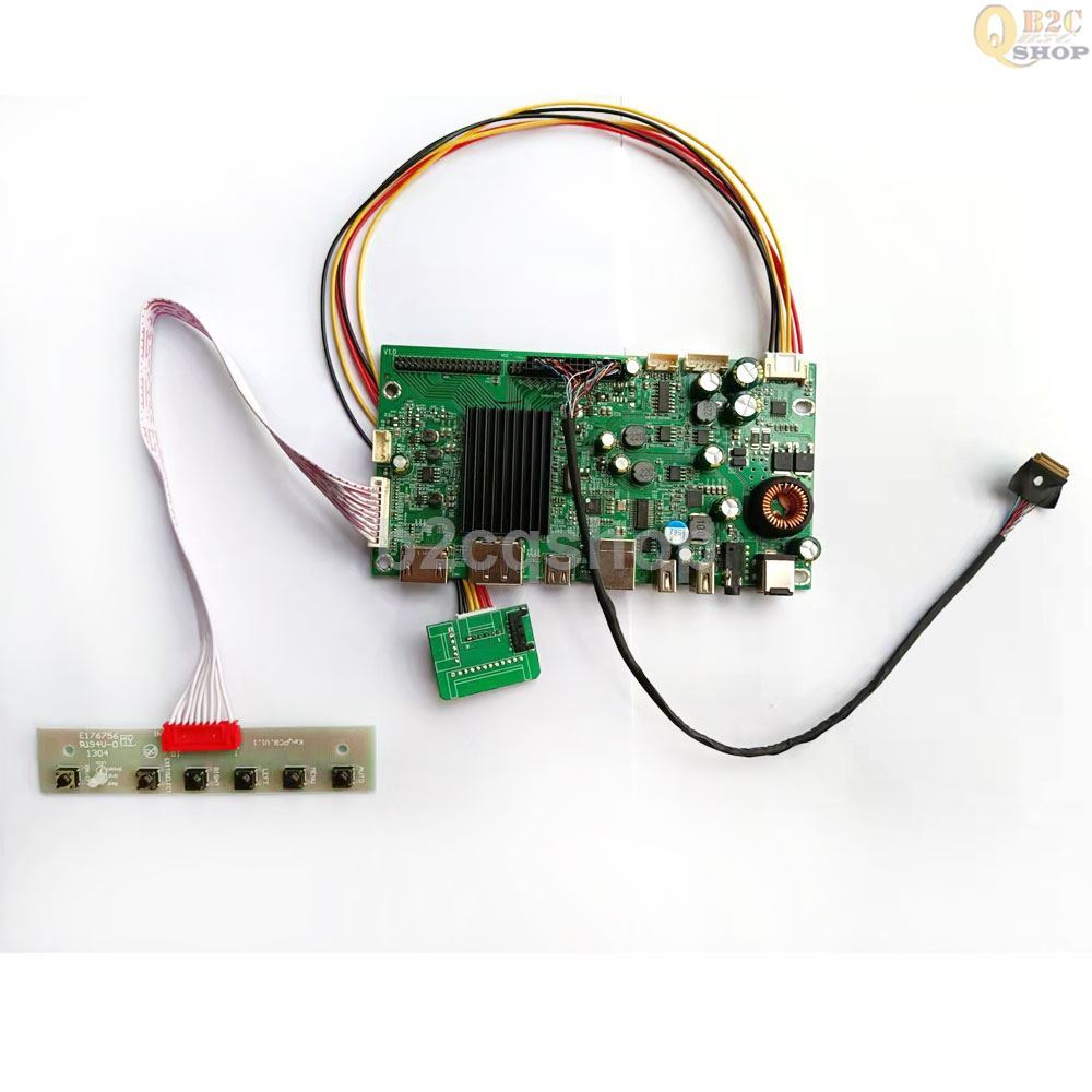
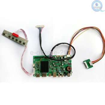
Bought this LCD driver kit for the display: https://www.ebay.com/itm/234456756136
I plan to mount this where the superdrive was. There is a cheaper option available, but that one has 2 separate PCBs, this one seems to include everything in one neat package. And i like the idea of having USB-C.

This driver needs a 24V / 5A power supply. I bought this one: https://www.digikey.hu/en/products/detail/xp-power/LCS150US24/15666821
This will fit at the same place where the original power supply was, only slightly smaller. I would need to 3d print a bracket for it though, so i can use at least 2 screws to fit it on place

The OSD buttons, i plan to mount them where the ram slot is. I will create a 3d print for this, so it can be screwed in the same way as the original ram cover. Found a model in Thingiverse, so i can modify this to fit.
The original power button can be connected to the on/off button on the OSD board, its a simple push button.
The tricky part is the ports. My idea is to create a PCB that kinda looks like this:

I measured everything and created a 3d model for now, but i will look for someone who can create a working PCB based on these(maybe you can help?). This board can be mounted where the original ports are. 2 USB A ports are coming from the LCD Driver board. The third USB A is the USB B connector on the LCD board(i mean its the same thing, just a different form-factor. If needed, one can use an USB-A -> USB-B adapter). A mini-hdmi connector will fit in the 4th USB port, this obviously connects to the HDMI port on the LCD board. I think its a good idea to go with mini-hdmi, this way we don't need to cut an extra hole(or enlarge an extra hole) on the iMac. And an hdmi-minihdmi cable is not expensive at all. Based on my calculations, the USB-C socket will fit in place of the firewire connector perfectly. This way we don't need to cut any extra holes, the existing ports will works just fine.
The other side of the PCB will look like this:

In theory, we could use a short male-male hdmi and usb-c cables to connect the doughter board to the LCD driver board. For USB, we can use a male USB to 5 pin dupont/molex header(this is cheaper than male-male short usb cable). As you can see, i want to use the existing speakers and at least once of the fans, probably the CPU fan, so it can cool the power supply. For the speakers, i found the correct receptacle. Left speaker is 5 pin(only 4 used though), right one is 4 pin. It is a Molex Pico-SPOX, part number 874380543 and 874380443. So we can connect the speakers without the need to modify the connectors on them. These speakers are 2 channel(woofer+tweeter) 15W. Looked up the schemantics for the logic board and Apple used 2 separate amps for the speakers, part number TPA3117D2. These are still available, but we can look for cheaper options, or maybe a single amp that can handle all 4 speakers. The amps are connected to the 4 PIN header, and then we can connect that to the LCD board audio output.
Tricky parts is the fans. Apple uses a 4 pin fan and based on my research its not easy to control the RPM of these fans. Another issue is that the fans are 12V and our power supply is 24V. If we are lucky, maybe the LCD driver board will have a 12V output somewhere, otherwise we need some extra stuff on the daughter board. I will check once i receive the driver board. Here is the schematics for the fans:

If someone can figure out an easy way to power this fan at the lowest RPM(1000) easily, let me know... The CPU fan cable is not long enough to reach the daughter board, so that needs to be extended with a connector.
One more 3d print is necessary for the mounting of the daughter board: on the original motherboard, all of the ports are angled at 70 degrees instead of normal 90degree ports. So a 3d printed peace will be necessary that can fix the PCB in place at an angle. Thats why we need to go with a double sided PCB sadly(this is more expensive), because of the angle, the components won't fit.
We can also re-use the existing headphone jacks. I found the connector that apple used for these on the original motherboard, but sadly its not available anymore.

We can cut the original connector off and simply hook up a 3.5mm jack. Found the wiring in the schematics:

So in theory we can connect AUD_LI_GND_JACK+AUD_HP_GND_JACK with our ground, AUD_LI_R_JACK+AUD_HP_R_JACK with right audio, and AUD_LI_L_JACK+AUD_HP_L_JACK for left audio and just connect it to the LCD driver board 3.5mm jack. This way you can use either or both audio ports on the iMac for headphones.
So this is where i am at the moment. Let me know if you are working or worked on a similar project and share ideas how can this be improved.
Recently got a 2009 iMac with a broken GPU and PSU, but the screen is fine. Ideal to convert this to an external display. I found multiple people doing this, but i find it that its not perfect and requires a lot of modification, so i want to create a "simpler way". I want this thread to be somewhere where we can brainstorm, share ideas and solutions. Before you start with this, keep in mind that this is better as a hobby project, because probably you can find a similar monitor cheaper(except if you like the glossy panel better than regular displays, which i do).
So i put a lot of thoughts into this and so far this is what i came up with. Let me know if you have other ideas to improve this. This is still a work in progress project, as i just started to order parts for it, but wanted to write it as a small journey.
Removed everything that was not necessary, so i have a blank shell. I kept the power button and 2 speakers.
Bought this LCD driver kit for the display: https://www.ebay.com/itm/234456756136
I plan to mount this where the superdrive was. There is a cheaper option available, but that one has 2 separate PCBs, this one seems to include everything in one neat package. And i like the idea of having USB-C.
This driver needs a 24V / 5A power supply. I bought this one: https://www.digikey.hu/en/products/detail/xp-power/LCS150US24/15666821
This will fit at the same place where the original power supply was, only slightly smaller. I would need to 3d print a bracket for it though, so i can use at least 2 screws to fit it on place
The OSD buttons, i plan to mount them where the ram slot is. I will create a 3d print for this, so it can be screwed in the same way as the original ram cover. Found a model in Thingiverse, so i can modify this to fit.
The original power button can be connected to the on/off button on the OSD board, its a simple push button.
The tricky part is the ports. My idea is to create a PCB that kinda looks like this:
I measured everything and created a 3d model for now, but i will look for someone who can create a working PCB based on these(maybe you can help?). This board can be mounted where the original ports are. 2 USB A ports are coming from the LCD Driver board. The third USB A is the USB B connector on the LCD board(i mean its the same thing, just a different form-factor. If needed, one can use an USB-A -> USB-B adapter). A mini-hdmi connector will fit in the 4th USB port, this obviously connects to the HDMI port on the LCD board. I think its a good idea to go with mini-hdmi, this way we don't need to cut an extra hole(or enlarge an extra hole) on the iMac. And an hdmi-minihdmi cable is not expensive at all. Based on my calculations, the USB-C socket will fit in place of the firewire connector perfectly. This way we don't need to cut any extra holes, the existing ports will works just fine.
The other side of the PCB will look like this:
In theory, we could use a short male-male hdmi and usb-c cables to connect the doughter board to the LCD driver board. For USB, we can use a male USB to 5 pin dupont/molex header(this is cheaper than male-male short usb cable). As you can see, i want to use the existing speakers and at least once of the fans, probably the CPU fan, so it can cool the power supply. For the speakers, i found the correct receptacle. Left speaker is 5 pin(only 4 used though), right one is 4 pin. It is a Molex Pico-SPOX, part number 874380543 and 874380443. So we can connect the speakers without the need to modify the connectors on them. These speakers are 2 channel(woofer+tweeter) 15W. Looked up the schemantics for the logic board and Apple used 2 separate amps for the speakers, part number TPA3117D2. These are still available, but we can look for cheaper options, or maybe a single amp that can handle all 4 speakers. The amps are connected to the 4 PIN header, and then we can connect that to the LCD board audio output.
Tricky parts is the fans. Apple uses a 4 pin fan and based on my research its not easy to control the RPM of these fans. Another issue is that the fans are 12V and our power supply is 24V. If we are lucky, maybe the LCD driver board will have a 12V output somewhere, otherwise we need some extra stuff on the daughter board. I will check once i receive the driver board. Here is the schematics for the fans:
If someone can figure out an easy way to power this fan at the lowest RPM(1000) easily, let me know... The CPU fan cable is not long enough to reach the daughter board, so that needs to be extended with a connector.
One more 3d print is necessary for the mounting of the daughter board: on the original motherboard, all of the ports are angled at 70 degrees instead of normal 90degree ports. So a 3d printed peace will be necessary that can fix the PCB in place at an angle. Thats why we need to go with a double sided PCB sadly(this is more expensive), because of the angle, the components won't fit.
We can also re-use the existing headphone jacks. I found the connector that apple used for these on the original motherboard, but sadly its not available anymore.
We can cut the original connector off and simply hook up a 3.5mm jack. Found the wiring in the schematics:
So in theory we can connect AUD_LI_GND_JACK+AUD_HP_GND_JACK with our ground, AUD_LI_R_JACK+AUD_HP_R_JACK with right audio, and AUD_LI_L_JACK+AUD_HP_L_JACK for left audio and just connect it to the LCD driver board 3.5mm jack. This way you can use either or both audio ports on the iMac for headphones.
So this is where i am at the moment. Let me know if you are working or worked on a similar project and share ideas how can this be improved.
Attachments
Last edited: