Heads up, it's a bit of a geek talk with some basic circuitry involved.
I got sick of manually controlling my fan speeds via a controller, so I decided to move the fans to the CPU headers. Unfortunately all of my fans are 3-pin, and my motherboard only goes to 60% duty cycle on 3-pin DC mode. On the other hand the PWM mode goes down to 20% and has much more freedom with the temperature-duty curve.
So I read up on how to make a 3-pin fan work like a 4-pin fan. At its core, both fans are driven by a DC motor with a tachometer sensor connected to the ground wire and the motherboard tach sensor. The driving voltage is 12V; by Intel specifications the PWM signal is 5.25V at 25kHz.
And I wasn't the only one who was thinking of the same thing. A thread at Techpowerup looked into the same thing, and the debate at the bottom of the thread had me thinking: NPN transistors work by having the base voltage biased towards either above or below the input voltage, and since the PWM, input and fan voltages are set at 0/5.25V (on/off), 12V and 12V respectively, a normal NPN transistor with the PWM on the base will result in full speed at all times.
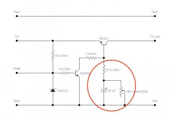
Instead, I was thinking the same thing as what the other commenter suggested in the thread: use an n-MOSFET which isolates the gate voltage from the input/output line, allowing control of the 12V flow without having the 0/5.25V of the PWM signal be affected by the 12V line. He also suggested putting the MOSFET on the ground, as does this article (although it uses a power transistor which again I don't think will work here).
I'm thinking of using a combination of the two by replacing the transistor in that article with a n-MOSFET with a threshold voltage of <4V and simplifying the circuit by removing the capacitor filter, at least to begin with. The question is then,
1. Will that work?
2. Does the tachometer work by measuring the ripple on the 12V line (i.e. is the resistor from the 12V line to the tach in required)? **see below
3. If the tachometer is constructed so, is it better to connect the MOSFET to the fan's 12V input then short the tach line to the 12V rail and ground? **see below
4. Am I in the right forum? lol
Edit: I'm reading up on the tach specifications, and it seems it's also a +5V square wave output. Looks like I'll have to read up a little more on how to have the tach signal work.
I got sick of manually controlling my fan speeds via a controller, so I decided to move the fans to the CPU headers. Unfortunately all of my fans are 3-pin, and my motherboard only goes to 60% duty cycle on 3-pin DC mode. On the other hand the PWM mode goes down to 20% and has much more freedom with the temperature-duty curve.
So I read up on how to make a 3-pin fan work like a 4-pin fan. At its core, both fans are driven by a DC motor with a tachometer sensor connected to the ground wire and the motherboard tach sensor. The driving voltage is 12V; by Intel specifications the PWM signal is 5.25V at 25kHz.
And I wasn't the only one who was thinking of the same thing. A thread at Techpowerup looked into the same thing, and the debate at the bottom of the thread had me thinking: NPN transistors work by having the base voltage biased towards either above or below the input voltage, and since the PWM, input and fan voltages are set at 0/5.25V (on/off), 12V and 12V respectively, a normal NPN transistor with the PWM on the base will result in full speed at all times.
Instead, I was thinking the same thing as what the other commenter suggested in the thread: use an n-MOSFET which isolates the gate voltage from the input/output line, allowing control of the 12V flow without having the 0/5.25V of the PWM signal be affected by the 12V line. He also suggested putting the MOSFET on the ground, as does this article (although it uses a power transistor which again I don't think will work here).
I'm thinking of using a combination of the two by replacing the transistor in that article with a n-MOSFET with a threshold voltage of <4V and simplifying the circuit by removing the capacitor filter, at least to begin with. The question is then,
1. Will that work?
2. Does the tachometer work by measuring the ripple on the 12V line (i.e. is the resistor from the 12V line to the tach in required)? **see below
3. If the tachometer is constructed so, is it better to connect the MOSFET to the fan's 12V input then short the tach line to the 12V rail and ground? **see below
4. Am I in the right forum? lol
Edit: I'm reading up on the tach specifications, and it seems it's also a +5V square wave output. Looks like I'll have to read up a little more on how to have the tach signal work.
Last edited: