My cousin is trying to connect an Ecobee 3 to his Carlin 60200 and Buderus boiler. The system does not have a C wire and he is not sure where to connect the power extender kit to on the system. What we believe to be the control panel on the Carlin is labeled T,T,F,F,A,A instead of the usual thermostat labeled wires (W, Y, G, Rc, R, C). Does anybody have any experience with this type of system and hooking up a smart thermostat? Or are there any other workarounds that are easy and will not damage the system?
Got a tip for us?
Let us know
Become a MacRumors Supporter for $50/year with no ads, ability to filter front page stories, and private forums.
Ecobee 3 with Carlin and Buderus Boiler
- Thread starter nunes013
- Start date
- Sort by reaction score
You are using an out of date browser. It may not display this or other websites correctly.
You should upgrade or use an alternative browser.
You should upgrade or use an alternative browser.
Yeah good idea! He took one and sent it to me. This gives a better idea.Maybe take a picture and post it here?
Attachments
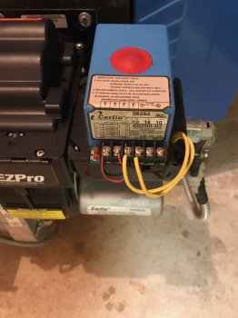

Your first photo shows the oil burner control. Don't touch that!
Your second photo shows thermostat wiring which appears to be controlling a simple heat-only boiler with a Green common ("C") wire. If I'm right, you're all set to install the Ecobee without extra gizmos.
The thermostat connects to a switching relay which I've seen mounted either on the wall or on the side of the boiler.
It's probably either a Taco or a Honeywell, though Buderus might have their own (could be labeled Bosch, too). Find it, take the cover off, and it might be obvious what your connections are. If not, post a picture, and I might be able to help.
Just to add - the switching relay connects the low voltage 24V thermostat to the boiler which uses 120V house current. It might be prudent to shut off the boiler at the emergency switch upstairs before opening the switching relay cover.
Last edited:
If it's a boiler, as the OP says, then it doesn't have a fan. That's why I assumed the extra wire is common.
A very common switching relay for a single stage heating-only FHW system is the Taco SR501, which has three thermostat connections: Red, White, and Common. Seeing three wires, and reading "boiler", I assumed, perhaps incorrectly, that was what I was seeing here.
Actually, looking more carefully at the picture of the thermostat wiring, that appears to be an air-conditioning thermostat, not a heating thermostat. Heat should use R and W. A/C uses RC and Y, as shown here. And if it is an A/C thermostat, then you're right, G is the fan.
OP, does your cousin have separate thermostats for heating and cooling?
Right, I was wondering why there'd be a G terminal too. Noticed the Y as well but didn't realize it could be a separate thermostat hahaIf it's a boiler, as the OP says, then it doesn't have a fan. That's why I assumed the extra wire is common.
A very common switching relay for a single stage heating-only FHW system is the Taco SR501, which has three thermostat connections: Red, White, and Common. Seeing three wires, and reading "boiler", I assumed, perhaps incorrectly, that was what I was seeing here.
Actually, looking more carefully at the picture of the thermostat wiring, that appears to be an air-conditioning thermostat, not a heating thermostat. Heat should use R and W. A/C uses RC and Y, as shown here. And if it is an A/C thermostat, then you're right, G is the fan.
OP, does your cousin have separate thermostats for heating and cooling?
The thermostat connects to a switching relay which I've seen mounted either on the wall or on the side of the boiler.
It's probably either a Taco or a Honeywell, though Buderus might have their own (could be labeled Bosch, too). Find it, take the cover off, and it might be obvious what your connections are. If not, post a picture, and I might be able to help.
Hey! Thanks for posting this. I have the same set-up as the original poster. I'm, however, unable to find the switching relay you describe. Is it 100% certain that there would be one? If so, I'll look harder. I'm in an old brownstone, so it might have been mounted anywhere.
Thanks again,
G.
Hey! Thanks for posting this. I have the same set-up as the original poster. I'm, however, unable to find the switching relay you describe. Is it 100% certain that there would be one? If so, I'll look harder. I'm in an old brownstone, so it might have been mounted anywhere.
Thanks again,
G.
It's not 100% certain you have a switching relay. In HVAC, especially in older buildings, nothing is 100% certain. I've seen people post pictures of multiple components inside their HVAC unit which provided the same functionality as a switching relay, spread out in a confusing mess.
I assume you've taken the cover off your current thermostat (model?), and determined you don't have a "C" wire. What wires do you have? Can you post a picture?
If you've got a 24V thermostat and 120V power going to the boiler, then somewhere there must be a 120V to 24V transformer. Find that transformer, and your thermostat connections should be nearby. Once you find the transformer, though, it may only confirm you need to do additional work to get power to the ecobee. If so, that may or may not be a DIY task.
Any pictures of your boiler, nearby wiring, and related accessories (zone valves, circulators, etc), will help.
There's an ecobee subreddit (https://www.reddit.com/r/ecobee/) where there is more knowledgeable help than I can provide. The ecobee website has a knowledge base covering a multitude of scenarios. And people say ecobee themselves are very helpful if you call them.
Thank you for the detailed and quick response! Greatly appreciated.
Will check out Reddit and come back to this thread with photos.
Thanks again,
G.
I have a Buderus boiler in my home. I just bought a 24V transformer and plugged it in near the boiler and pulled the wires to the thermostat. The transformer I got looks like this:
https://www.amazon.com/MG-ELECTRONI...id=1512517211&sr=8-8&keywords=24v+transformer
https://www.amazon.com/MG-ELECTRONI...id=1512517211&sr=8-8&keywords=24v+transformer
As an Amazon Associate, MacRumors earns a commission from qualifying purchases made through links in this post.
Its definitely possible however it will be more of an "advanced" setup. Typically people can go wire for wire and have these install in less then 30 minutes. I filled holes and repainted the wall behind the thermostat and it took me 45 minutes.
You are missing a picture of the boilers thermostat though.
The second picture is showing Rc (24volt cooling transformer), a white wire connected to Y (cool relay) and G (fan relay). The W (heat relay) is the only terminal on that thermostat that controls the heat which is has nothing connected to it so there is another thermostat for the Buderus in the house.
The first picture is the boilers primary control. Although that isn't the most modern boiler rarely does a boiler use the TT (thermostat terminals) connections as once intended. They are jumped together so the thermostat likely wires to the boilers aquastat to TT (thermostat terminals) which interns sends 120volt to the burner and since the primary TT is jump out it comes on.
The EcoBee (and other smart thermostats) need C (Common) to power themselves (thermostat shown has batteries). C (Common) is the return voltage to complete the circuit, although inaccurate you could think of it as a neutral in this case. This is required because the screen, wifi, etc draw too much power for a couple AA batteries.
However I think I see another another conductor behind the wall on the thermostat (a blue wire maybe?). If I'm seeing that correctly that is a good think and you'll need it.
This is what needs to be done.
Turn the power off to the boiler and the part of the AC that houses the low voltage transformer. In a traditional split system (air handler/blower unit inside and AC outside) it is in the AIR HANDLER, not the AC. But make sure BOTH breakers are turned off for the AC to be safe (it will be 2 x 2 Pole breakers). This is important because its really easy to fry a transformer (or blow its fuse if it has one). I would suggest putting the thermostat back on, setting the fan to run and turn off the breakers then verify the fan has shut off. The boiler will be much easier, switch at the top of the basement steps and/or on the side of the boiler.
The thermostat wire from the boiler and thermostat wire from the air handler need splice together or run to the Ecobee's mounting location.
The two wires coming from the boiler (typically red and white are used but color doesn't matter if its an old house it could be brown and brown cloth wires) need to connect to Rh (24volt heat) and W (heat relay) on the EcoBee.
Then you'll need to goto the air handler, find the thermostat wire (small brown wire) remove the cover it runs into. See if there is an extra conductor not being used in the wire (again appears to be behind the thermostat). That unused conductor needs to connect to C on the air handler.
Then at the Ecobee the wires from the air handler will be Red to Rc, White to Y (cool) (typically a yellow conductor is used but there wasnt one there so white was used), Green to G (fan) and that new wire connected to C in the air handler goes to C on the Ecobee.
Here is a schematic I drew up real quick to hopefully help you out.

Excuse my hand writing. That Y wire is jumping over the G wire, not connected together.
Don't concern yourself with the colors of the wires, that is arbitrary and since there isn't a yellow already Y is using a white wire. However do not get them confused, if the boiler is using red and white and you mix up the wires you can possibly damage something and if you damage an aquastat you could be out a few hundred to repair it.
If I was mistaken and there isn't an extra conductor for C (Common) behind the thermostat you will need to run a new wire or sacrifice G (fan) and have no manual fan control (fan will energize with a call for cooling). The included add-a-wire solution (PEK - Power Extender Kit) will NOT work in this circumstance because it uses the wire for the cooling (Y) and heating (W) as a common when they are not being used.
Pulling a new wire from the air handler would be the best way of doing it however to avoid that and sacrifice the G (fan) wire...
Do the same as above except at the air handler instead of connecting the extra conductor (blue?) to C (Common) you will move the green wire from the G (fan) terminal to the C (Common) in the air handler. Then you will connect that green wire to C (Common) at the thermostat. Than take a small piece of thermostat wire (pull a piece off the included PEK unit if you can't spare any in the air handler) and jump G and Y inside of the air handler.

Again excuse my handwriting, I know its embarrassingly bad but it would have taken me much longer to use a program or app.
So any time the Y (cool) terminal is energized the G (fan) terminal will be too. However since there is nothing connected to G (fan) at the thermostat manually setting the fan to run will do nothing. I believe in the setup of the thermostat you can even disable it as an option you access from the thermostat (equipment controls fan).
TL;DR : Call a professional... lol...
You are missing a picture of the boilers thermostat though.
The second picture is showing Rc (24volt cooling transformer), a white wire connected to Y (cool relay) and G (fan relay). The W (heat relay) is the only terminal on that thermostat that controls the heat which is has nothing connected to it so there is another thermostat for the Buderus in the house.
The first picture is the boilers primary control. Although that isn't the most modern boiler rarely does a boiler use the TT (thermostat terminals) connections as once intended. They are jumped together so the thermostat likely wires to the boilers aquastat to TT (thermostat terminals) which interns sends 120volt to the burner and since the primary TT is jump out it comes on.
The EcoBee (and other smart thermostats) need C (Common) to power themselves (thermostat shown has batteries). C (Common) is the return voltage to complete the circuit, although inaccurate you could think of it as a neutral in this case. This is required because the screen, wifi, etc draw too much power for a couple AA batteries.
However I think I see another another conductor behind the wall on the thermostat (a blue wire maybe?). If I'm seeing that correctly that is a good think and you'll need it.
This is what needs to be done.
Turn the power off to the boiler and the part of the AC that houses the low voltage transformer. In a traditional split system (air handler/blower unit inside and AC outside) it is in the AIR HANDLER, not the AC. But make sure BOTH breakers are turned off for the AC to be safe (it will be 2 x 2 Pole breakers). This is important because its really easy to fry a transformer (or blow its fuse if it has one). I would suggest putting the thermostat back on, setting the fan to run and turn off the breakers then verify the fan has shut off. The boiler will be much easier, switch at the top of the basement steps and/or on the side of the boiler.
The thermostat wire from the boiler and thermostat wire from the air handler need splice together or run to the Ecobee's mounting location.
The two wires coming from the boiler (typically red and white are used but color doesn't matter if its an old house it could be brown and brown cloth wires) need to connect to Rh (24volt heat) and W (heat relay) on the EcoBee.
Then you'll need to goto the air handler, find the thermostat wire (small brown wire) remove the cover it runs into. See if there is an extra conductor not being used in the wire (again appears to be behind the thermostat). That unused conductor needs to connect to C on the air handler.
Then at the Ecobee the wires from the air handler will be Red to Rc, White to Y (cool) (typically a yellow conductor is used but there wasnt one there so white was used), Green to G (fan) and that new wire connected to C in the air handler goes to C on the Ecobee.
Here is a schematic I drew up real quick to hopefully help you out.
Excuse my hand writing. That Y wire is jumping over the G wire, not connected together.
Don't concern yourself with the colors of the wires, that is arbitrary and since there isn't a yellow already Y is using a white wire. However do not get them confused, if the boiler is using red and white and you mix up the wires you can possibly damage something and if you damage an aquastat you could be out a few hundred to repair it.
If I was mistaken and there isn't an extra conductor for C (Common) behind the thermostat you will need to run a new wire or sacrifice G (fan) and have no manual fan control (fan will energize with a call for cooling). The included add-a-wire solution (PEK - Power Extender Kit) will NOT work in this circumstance because it uses the wire for the cooling (Y) and heating (W) as a common when they are not being used.
Pulling a new wire from the air handler would be the best way of doing it however to avoid that and sacrifice the G (fan) wire...
Do the same as above except at the air handler instead of connecting the extra conductor (blue?) to C (Common) you will move the green wire from the G (fan) terminal to the C (Common) in the air handler. Then you will connect that green wire to C (Common) at the thermostat. Than take a small piece of thermostat wire (pull a piece off the included PEK unit if you can't spare any in the air handler) and jump G and Y inside of the air handler.
Again excuse my handwriting, I know its embarrassingly bad but it would have taken me much longer to use a program or app.
So any time the Y (cool) terminal is energized the G (fan) terminal will be too. However since there is nothing connected to G (fan) at the thermostat manually setting the fan to run will do nothing. I believe in the setup of the thermostat you can even disable it as an option you access from the thermostat (equipment controls fan).
TL;DR : Call a professional... lol...
Will check out Reddit and come back to this thread with photos.
Hi All,
Thank you for posting the detailed information. We definitely do not have a C wire running from the boiler. We also don't have a 24v transformer anywhere near the boiler. So I've purchased the one recommended earlier in the thread.
https://www.amazon.com/gp/product/B0010GR07O/ref=oh_aui_detailpage_o00_s00?ie=UTF8&psc=1
Question: Does someone have an image of one of these connected to their Ecobee 4? Do I need to run a wire from each terminal on the transformer to the C connection on the Ecobee in order to complete the circuit? Or will just one suffice?
I've also attached the photos of our set-up, for reference.


Thanks again,
G.
As an Amazon Associate, MacRumors earns a commission from qualifying purchases made through links in this post.
Hi All,
Thank you for posting the detailed information. We definitely do not have a C wire running from the boiler. We also don't have a 24v transformer anywhere near the boiler. So I've purchased the one recommended earlier in the thread.
https://www.amazon.com/gp/product/B0010GR07O/ref=oh_aui_detailpage_o00_s00?ie=UTF8&psc=1
Question: Does someone have an image of one of these connected to their Ecobee 4? Do I need to run a wire from each terminal on the transformer to the C connection on the Ecobee in order to complete the circuit? Or will just one suffice?
I've also attached the photos of our set-up, for reference.
View attachment 741218 View attachment 741219 View attachment 741220
Thanks again,
G.
I highly recommend just calling a professional based on your questions.
The purpose of Rc and Rh on a thermostat is isolate the 2 transformers and you are attempting to add a 3rd.
"Common" is only relative to its own source when referenced in this circumstance. The terminals that actually power the thermostat are Rc and C. Rc is 24 volt from the air handlers transformer and C is that transformers common. Since the air handler likely has a grounded common if you measure voltage on Rc to ground you'll have ~24 volts, measure C to ground and you'll have 0 volts, between them you'll have ~24 volts.
That transformer you bought has 2 terminals. Since its AC (alternating current) and its clearly not grounded for a ground common you'll have voltage to ground on both terminals when measured to ground.


And between them you'll have 24 volts (step down voltage, since I have 127 volts in I have higher than 24 volts out).

Connected either/both terminal to C on the thermostat isn't completing the circuit, that would just be adding another incomplete circuit with a much higher likelihood of damaging something.
As an Amazon Associate, MacRumors earns a commission from qualifying purchases made through links in this post.
Register on MacRumors! This sidebar will go away, and you'll see fewer ads.