Inspired by others that have trailblazed the path before me, I am venturing into the “iMac G4 to Mac mini M1 mod/conversion” landscape, and will document my journey in this thread.
During my tinkering with old iMacs, I have always been grateful when others have taken the time to document their doings, in detail, and thereby contributing to the collected knowledge base around iMac G4 matters, so I find it appropriate to do the same, with the hope that someone can be helped by this.
I will try to be as specific as possible, and share as much details, links etc about components, wirings, configurations etc as I can. I know first hand how frustrating it can be when vital information is left out in guides/descriptions on how to do these kind of things, and my goal is to describe what I do so that “anyone” should be able to follow the same steps. (I am kind of assuming here that I eventually will succeed") )
)
This will most likely take a few months or so, taking into consideration the waiting time to get parts shipped from elswhere + I have other hobbies + the fact that I am not really sure how to pull this off. I have plenty of experience tinkering with G4s, but feel a bit at loss when it comes to wiring/splicing power cables and voltage converters…but how hard can it be? ;-)
Inspiration comes from several people. I guess it started seeing what the legendary Dremeljunkie did a decade ago, and then the recent feat by colbyjjohn94 really ignited my desire to actually do something similar myself. And there are others, both from this forum and elsewhere that have inspired: Macaron, connor55, PML7554, gagigu and just the other day I found Albino Rifici (audio & text all in Italian, so I used auto translate, and it became half-comprehensible for me who don't speak that language)
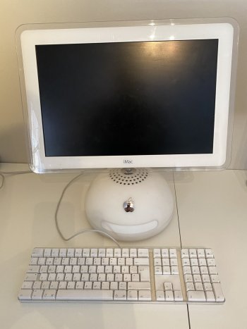
So, to start with I had to decide which iMac to mod. I have all G4 sizes, (Four 15”, three 17” and two 20”). The 15” is too small and I don’t want to destroy any of my fully functional 20”s. As it happens, one of the 17”s have been throwing kernel panics with probable hardware cause, so I decided to sacrifice this faulty 17”. Contributing to this decision was also the fact that there exists replacement LCDs with the correct form factor (16:10) and with higher resolution than the original.
So as of right now my mod plan looks like this:
The iMac I am using is this model: https://everymac.com/systems/apple/imac/specs/imac_800_17_fp.html
A take-apart manual can be found here: https://tim.id.au/laptops/apple/imac/imac.17-inch.pdf
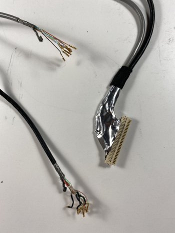
First step was to take apart the iMac G4, and then start ordering parts. Details will follow.
During my tinkering with old iMacs, I have always been grateful when others have taken the time to document their doings, in detail, and thereby contributing to the collected knowledge base around iMac G4 matters, so I find it appropriate to do the same, with the hope that someone can be helped by this.
I will try to be as specific as possible, and share as much details, links etc about components, wirings, configurations etc as I can. I know first hand how frustrating it can be when vital information is left out in guides/descriptions on how to do these kind of things, and my goal is to describe what I do so that “anyone” should be able to follow the same steps. (I am kind of assuming here that I eventually will succeed
)This will most likely take a few months or so, taking into consideration the waiting time to get parts shipped from elswhere + I have other hobbies + the fact that I am not really sure how to pull this off. I have plenty of experience tinkering with G4s, but feel a bit at loss when it comes to wiring/splicing power cables and voltage converters…but how hard can it be? ;-)
Inspiration comes from several people. I guess it started seeing what the legendary Dremeljunkie did a decade ago, and then the recent feat by colbyjjohn94 really ignited my desire to actually do something similar myself. And there are others, both from this forum and elsewhere that have inspired: Macaron, connor55, PML7554, gagigu and just the other day I found Albino Rifici (audio & text all in Italian, so I used auto translate, and it became half-comprehensible for me who don't speak that language)
So, to start with I had to decide which iMac to mod. I have all G4 sizes, (Four 15”, three 17” and two 20”). The 15” is too small and I don’t want to destroy any of my fully functional 20”s. As it happens, one of the 17”s have been throwing kernel panics with probable hardware cause, so I decided to sacrifice this faulty 17”. Contributing to this decision was also the fact that there exists replacement LCDs with the correct form factor (16:10) and with higher resolution than the original.
So as of right now my mod plan looks like this:
- One not-so-well-functioning iMac G4 17” will be sacrificed
- Target transplant is Mac mini M1. Currently trying to find one with 16GB RAM + at least 512GB SSD at reasonable price to strip down.
- Display will be upgraded to one with higher resolution than original (1920x1200 instead of 1440x900)
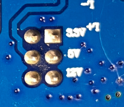
- As for the original Power Supply Unit , I initially thought about keeping that, but after some consideration decided against it. I wish to modernize the innards as much as possible while I am at it. The PSU is 20+ years old, and though it works fine right here and now, I rather not take the risk of having to re-do that part due to capacitors starting to leak etc within a year or three..
- The DVD player was not really functioning, so that will not be kept. If I pull this conversion off and I go for another conversion in the future, I may change my mind if there is a functioning DVD.
- I really want to keep the original power button
- Ports should be kept intact, but “upgraded” in terms of what is behind them. Not decided yet on what to offer there though, but I see no panic to decide that.
- The audio port + ability to use the original Apple Pro speakers will be a stretch goal. I have not read enough about how to make it work to say at this stage if I will try it or not.
- As for the internal speaker, I may keep that, with the same caveat as for the audio port: don't know how easy or worthwhile it would be.
- The original fan is also optional, but as it is not really in the way where it is, I strongly consider keeping that.
- The microphone in the display bezel would be nice-to-have operational, but also optional, with same caveats as for fan and internal speaker.
- I would also really like to have the LED indicator in the display bezel to work.
The iMac I am using is this model: https://everymac.com/systems/apple/imac/specs/imac_800_17_fp.html
A take-apart manual can be found here: https://tim.id.au/laptops/apple/imac/imac.17-inch.pdf
First step was to take apart the iMac G4, and then start ordering parts. Details will follow.
Attachments

Last edited: