Got a tip for us?
Let us know
Become a MacRumors Supporter for $50/year with no ads, ability to filter front page stories, and private forums.
Mod G4 iMac with Intel Mac mini innards?
- Thread starter casesensitive
- Start date
- Sort by reaction score
You are using an out of date browser. It may not display this or other websites correctly.
You should upgrade or use an alternative browser.
You should upgrade or use an alternative browser.
pmackin
macrumors member
inverter ??
I've looking at the manuals .. on the flat panel imac the lcd connects to a inver ter .. which connects to the lcd .
now my question is , could there be a way to get a cable from the dvi port of the mini and run it to the inverter ?
forget about routing the cable for now , but will this work electrically speaking.
Attachments
ericarthur
macrumors newbie
does anyone have the service manual for the iMac 15"? I saw it once and there was a wiring guide for the video wire. That would make a DVI adaptor much easier.
I've looking at the manuals .. on the flat panel imac the lcd connects to a inver ter .. which connects to the lcd .
now my question is , could there be a way to get a cable from the dvi port of the mini and run it to the inverter ?
forget about routing the cable for now , but will this work electrically speaking.
The inverter is to power the flourescent lamp (backlight). DVI is the signal.
Forget about power for now, thats a 10 second job, especially since the inverter is already in the display. It'll just need DC power (Probably 12v) and the correct DVI signal.
You say there are 12 pins?
Can I get a picture of the connector?
Well, something died inside of my 17" iLamp G4. When you push the power button absolutely nothing happens. A few hours later and I've got the thing completely dismantled and found this thread via google 🙂
I am hoping to be able to use the LCD as the primay display for my wife's G5 tower or a secondary monitor on my MacPro tower.
I have taken several photos of the connectors in question and hopefully someone a little more savvy than me can help us all solve the problem of driving one of these things with a VGA or DVI output from a computer.
I will see about posting those photos...
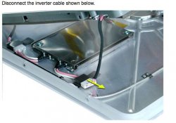
There are four main cables that exit the metal support arm. They are clearly in pairs, two apparently dealing with power. These two cables come from the motherboard via a 16 pin connector out to the fan, speaker and then into the LCD as well. One of the wires is clearly labeled "INVERTER CABLE"
The other pair is what I believe to be the video signal heading into the LCD. One cable is light gray, the other black. They come out of the support arm separatley but then terminate in a single connector which was attached to the motherboard.
It has 21 pins in two rows. One row with 11 the other with 10. The two cables are taped together with a label which reads 620-2305. The connector itself has the word "Foxconn" stamped into it on both sides. The metal bracket on the connector is just over 5/8" wide; the 11 pin side is 9/16"; the 10 pin side is 1/2". I hope this is helpful to someone 🙂
[*]
Thats going to be VGA/DVI then. It'll be DVI though.
Any pictures of the wires coming out of that connection? I need the colours of the wires, each individual wire that is. All 21.
If you want to see what the wires for each of the 21 pins look like, I have three choices:
1) Hack the two cables in half to expose the individual wires within each.
2) Attempt to expose the wires coming out of that connector by removing the plastic jacket near the connector itself.
3) Disassemble the LCD enclosure to see if the wires might be exposed on the other end.
I'm not particularly fond of 1, but that is surely the easiest way to do it.
Option 2 is likely to be the most reversible of the three options, but may or may not work.
Opening up the LCD enclosure is a gamble on whether the wires are even exposed.
fuyutsuki
macrumors newbie
I have a busted 800MHz Superdrive 15" iMac G4 I picked up for free recently and can verify what's just been said about the wiring. (Mine is DOA so I suspect the power supply and/or motherboard.)
The crucial connector is the silver coloured one photographed above, which is actually quite small and has 21 pins, clipping into its mate on the motherboard with a satisfying 'click'. There is also the second cable talked about which seems to be for power to the LCD and other devices along the way.
Now I also happen to have the service manual, and have just been Googling for data. Here's some of what I've come up with:
I don't know much about internal connections to digital displays, but which is more likely: this crucial 21 pin connector is VGA based like the secondary output or is something exotic linked to this specific screen?
As said by Stadsport on the other thread:
Damn! Sounds like it may be a better idea to remove the LCD and replace it with an identical sized (and maybe higher res) new one whose inputs are known.
Anyway, since I've been elbow deep inside my broken iMac several times I'd like to add the following notes:
Anyway, keep this project alive as I know there are many Sunflower Mac lovers out there, including latecomers like me, who want Intel power in a design classic case. May the hack be with you!
The crucial connector is the silver coloured one photographed above, which is actually quite small and has 21 pins, clipping into its mate on the motherboard with a satisfying 'click'. There is also the second cable talked about which seems to be for power to the LCD and other devices along the way.
Now I also happen to have the service manual, and have just been Googling for data. Here's some of what I've come up with:
The Geforce 2 graphics card does all the video scaling by itself, supporting fullscreen stretched resolutions at:
640x480 @ 60Hz
800x600 @ 75Hz
1024x768 @ 75Hz
The secondary output is a Mini VGA plug (14 pin) and supports mirror mode only, unless you use a firmware patch.
I don't know much about internal connections to digital displays, but which is more likely: this crucial 21 pin connector is VGA based like the secondary output or is something exotic linked to this specific screen?
As said by Stadsport on the other thread:
I had this idea a while ago, and after doing some research I found that not only does the iMac G4 use a wonky connector for the screen, but I'm pretty sure the LCD has no onboard image processor. The iMac's logic board handles the picture.
Damn! Sounds like it may be a better idea to remove the LCD and replace it with an identical sized (and maybe higher res) new one whose inputs are known.
Anyway, since I've been elbow deep inside my broken iMac several times I'd like to add the following notes:
- The iMac uses a full size parallel ATA hard drive and optical drive, which are master and slave on its single IDE channel.
- The hard drive and power supply share space right at the top of the dome, closest to the neck.
- Fitting a Mac Mini inside is quite possible on first glance, but NO WAY with a full size optical drive at the same time, however a 3.5" hard drive is probably fine.
- Inside the iMac case is a metal structure called the Faraday Cage which basically makes for a thicker shell, reducing the space from what you'd think
- The drive slot at the front is very easily made to open, so you don't need a perfect match to make it work, however a slot drive would need to be "helped" whenever you want to open the door without a disc already in the machine!
- Intel Mac Mini's have a large power supply brick which takes the same plug as the iMac but is too big to fit inside the case as well as a Mini, so an external cord trick would need to be used.
Anyway, keep this project alive as I know there are many Sunflower Mac lovers out there, including latecomers like me, who want Intel power in a design classic case. May the hack be with you!
This is pure speculation, but I would expect the signals between the iMac G4 mainboard and its LCD display are pretty much the same as the signals between a powerbook's mainboard and its LCD display.
Why would they bother putting DVI (or VGA) decoding circuitry on the LCD end of the arm if they didn't need to?
Why would they bother putting DVI (or VGA) decoding circuitry on the LCD end of the arm if they didn't need to?
fuyutsuki
macrumors newbie
This is pure speculation, but I would expect the signals between the iMac G4 mainboard and its LCD display are pretty much the same as the signals between a powerbook's mainboard and its LCD display.
Why would they bother putting DVI (or VGA) decoding circuitry on the LCD end of the arm if they didn't need to?
This sounds reasonable, so what's it like in the laptops then? Is there some sort of standard that raw data to TFT's is sent in? Is it something we could emulate?
My feeling is that if it's not easily done, it might be best to get hold of an equally sized standalone display (with DVI / VGA connector) and hack that into the Mac instead .. as the iMac's TFT is indeed removable with a little care. Whatever else goes in would need to match the iMac head quite nicely. But then again, it could also be of a higher pixel resolution than the iMac's lowly res. Interesting idea if it's do-able. Especially as a normal screen power supply should be able to fit inside the iMac base quite easily so long as it's not humongous ... especially if we're talking about turning the iMac into a display rather than a display with a Man Mini included in the package!
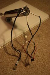
Here is a shot of all the cables coming from the metal support arm.

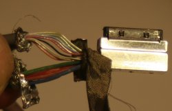
This is a picture of the exposed wires as they go into the connector. The colors are not completely true to life due to the lighting. The colors are as follows from top to bottom:
(Small wires) Yellow, Green, Blue, Purple, Red, Black, White, Gray, Orange
(Large Wires) Green, Red, Brown, Blue

This is a picture of the exposed wires as they go into the connector. The colors are not completely true to life due to the lighting. The colors are as follows from top to bottom:
(Small wires) Yellow, Green, Blue, Purple, Red, Black, White, Gray, Orange
(Large Wires) Green, Red, Brown, Blue
Attachments
fuyutsuki
macrumors newbie
Nice work. We'll have to see if anyone can tell us what they mean!
Hmm.... this is the most detailed snip from another thread:
The Wikipedia turfs this up under LDVS...
http://www.national.com/nationaledge/may01/lvds.html

I'm thinking ... ¿ay que lastima?
Hmm.... this is the most detailed snip from another thread:
The Wikipedia turfs this up under LDVS...
http://www.national.com/nationaledge/may01/lvds.html
I'm thinking ... ¿ay que lastima?
xyian
macrumors 6502
I really hope you all keep this project going strong!
I'm sorry I can't contribute to the cause here but I haven't
done any soldering since high school.
If you do get it up and running though, I will strongly consider
buying an old 20" iMac and attempting this(after much solder
practice, of course....)
Cheers!
I'm sorry I can't contribute to the cause here but I haven't
done any soldering since high school.
If you do get it up and running though, I will strongly consider
buying an old 20" iMac and attempting this(after much solder
practice, of course....)
Cheers!
fuyutsuki
macrumors newbie
Is it just me, or do the "18+3" wires going into the "TCON" on that diagram above sound a lot like the 21 pins on the video jack? 😉
There's also an 18+3 arrangement on the other side of the picture, right into the VGA (graphics card, which we know is on the iMac motherboard), but that side needs a separate clock signal.
In other news, no luck picking up a generic 15" TFT here to pursue the alternative.
There's also an 18+3 arrangement on the other side of the picture, right into the VGA (graphics card, which we know is on the iMac motherboard), but that side needs a separate clock signal.
In other news, no luck picking up a generic 15" TFT here to pursue the alternative.
R0ck1t
macrumors member
🙂 Excellent that someone else has had this brilliant Idea
I also own the iMac G4 (But 17" as no one seems to on this thread), I have opened it and had a look but have limited knowledge of computer functions.
I'll soon have Electronics & I.T GCSEs and would gladly help if anyone can think of a way I can.
P.S
If anyone knows of a way to upgrade the USB1.1 to USB2 or have an external hub I would be grateful if you shared this wisdom.
Cheers.
You need a controller between the LCD and the Mini VGA out. There is no way to directly connect the wires from the LCD to the Mini. The imac has this "controller" built into the logic board, as do most laptops. You can buy a controller "http://store.earthlcd.com/LCD-Products/Analog-VGA-Controller-Cards"
but they can get pricey. Second option might be to take apart a stand alone LCD monitor and borrow some parts, just watch the power outputs / inputs, would be easy to fry your good LCD Panel.
but they can get pricey. Second option might be to take apart a stand alone LCD monitor and borrow some parts, just watch the power outputs / inputs, would be easy to fry your good LCD Panel.
fuyutsuki
macrumors newbie
You need a controller between the LCD and the Mini VGA out. There is no way to directly connect the wires from the LCD to the Mini. The imac has this "controller" built into the logic board, as do most laptops. You can buy a controller "http://store.earthlcd.com/LCD-Products/Analog-VGA-Controller-Cards"
but they can get pricey. Second option might be to take apart a stand alone LCD monitor and borrow some parts, just watch the power outputs / inputs, would be easy to fry your good LCD Panel.
Nice link. This looks promising:
NK-GM2221-421 LCD Controller KIt
MultiMedia LCD Controller Kit
(includes everything but the LCD)
Call for LCD Compatability
Could someone in the US give them a call? As in ask if they know the iMac G4 and whether it's 15, 17 or 20" TFT is compatible with their board. I don't fancy crossing the Atlantic with my phone company, this is what the internet's for after all! 😉
Maxwell Smart
macrumors 6502a
This discussion looks promising. An intel mini inside an iMac G4 would be so cool, not only because of the obvious increase in performance and new RAM ceiling (of 3GB) but also because you could probably get a full size 3.5" hard drive inside, and can easily upgrade the mini's processor because it's socketed. Good Luck with this, unfortunately I don't have an iMac G4 otherwise I would try to contribute.
LDVS vs. TMDS
From what I can tell (and I know nothing) it probably does use LDVS (FPD-Link/LDI), but it could possibly use TMDS (DVI/HMDI/???). Some graphics chips have built-in TMDS senders, so I suppose Apple could have used it in the g4 imac if they had wanted to for some reason.
Even if we somehow determine it uses FPD-Link, there are 18-, 24-, and 48-bit senders and receivers. I would guess that Apple would use 24-bit, but what do I know? I guess we could look at the markings on the chips and see if there is anything to be discovered. For example, if we see a chip marked DS90CF384A on the display end of the arm, then we know it's 24-bit LVDI. (Though I guess it is possible that the sender was 18-bit instead.)
The thing is, there are sure to be people out there who know exactly what the g4 imac (and other iMac/eMac models) uses, if we could only find them.
Originally Posted by robbieduncan:
It's probably FPD-Link or maybe, but unlikely LDI. These are LDVS signalling technologies often used to connect flatpanel displays to graphics chips. The first is normal in laptops and probably the iMac too.
From what I can tell (and I know nothing) it probably does use LDVS (FPD-Link/LDI), but it could possibly use TMDS (DVI/HMDI/???). Some graphics chips have built-in TMDS senders, so I suppose Apple could have used it in the g4 imac if they had wanted to for some reason.
Even if we somehow determine it uses FPD-Link, there are 18-, 24-, and 48-bit senders and receivers. I would guess that Apple would use 24-bit, but what do I know? I guess we could look at the markings on the chips and see if there is anything to be discovered. For example, if we see a chip marked DS90CF384A on the display end of the arm, then we know it's 24-bit LVDI. (Though I guess it is possible that the sender was 18-bit instead.)
The thing is, there are sure to be people out there who know exactly what the g4 imac (and other iMac/eMac models) uses, if we could only find them.