Become a MacRumors Supporter for $50/year with no ads, ability to filter front page stories, and private forums.

simie

macrumors 65816
Original poster
Aug 26, 2004
1,192
71
Sitting
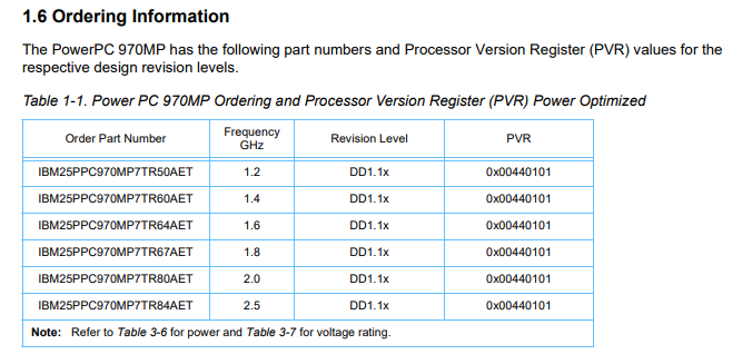
Hi everyone, I have was browsing eBay recently and noticed the amount of G5 970 Processors that are for sale and this got me wondering. So I have a theory about the overclocking of the CPU's after looking at the various boards.

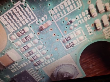
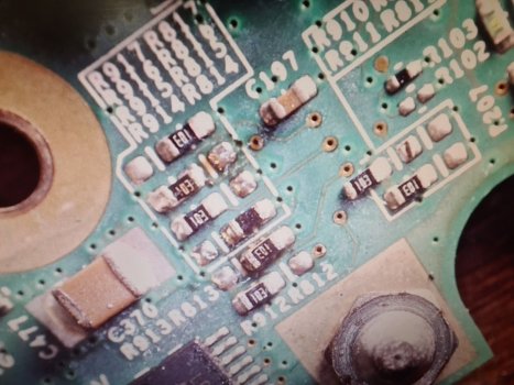
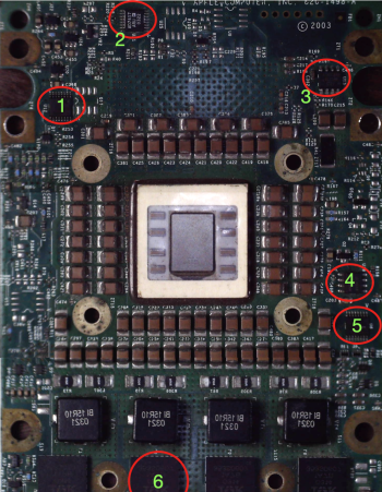
Just underneath board near the connector which attaches the daughterboard with the CPU on to the motherboard there is a bank of resistors and these are soldered differently on different boards. The other things that appears to change on the boards is the row of crystals (i presume that is what they are.)

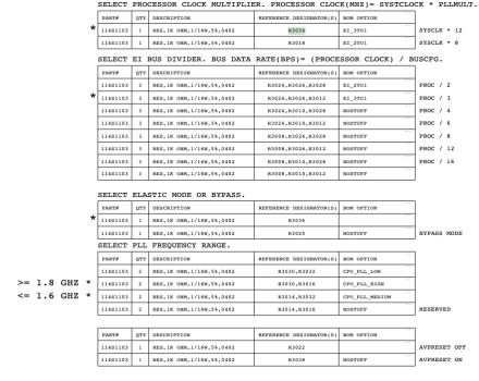
Going back to the resistors, there are six rows with 12 positions and these appear to be vary on different speed boards. I cannot test any of this because I do not have any of these boards to modify. So I presume that these resistors could be the multipliers and possibly the voltage to the 970 cpu.

Now if you guys can post any boards on here we can match and then test this theory of mine out.

I may have it all wrong, but here are some photos to back up my claim.

Processor 1.8 GHZ.jpg

Processor 2.0 GHZ.jpg

PPC 2.5Ghz.jpg


It may simple in all that we do is to resolder the resistors into a different order to achieve a higher frequency from the CPU's. One thing that I will state is that we all know that manufacturers use faster speed cpu's because of shortage and Apple struggled with IBM to get the supply of these CPU's.

Now we need someone to verify my claims or provide more information and perhaps we can figure out the combinations, if I have got this right.

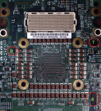
On the other side of the board there appears to be a row of crystals across the board, why these boards need all these I do not know at this stage. Some boards have more than others.

My next question is how will the firmware behave with a overclocked CPU or can this be modified as well. I presume that there may be restrictions of some sort but there will always be a work around.
 

Attachments

  • s-l1600.jpg
    s-l1600.jpg
    413.3 KB · Views: 188
  • s-l1600.jpg
    s-l1600.jpg
    375.2 KB · Views: 160
Last edited:

Written back in 2006 Original Article


Couple of suggestions for approaches that would take far less time...
1. Get a 1.8/2.0/2.2GHz processor module and copy the I2C PROM. This has all the work already done for you. Burning a higher speed image into a lower speed module would effectively yeild one half of an overclock mechanism. BACKUP EVERYTHING FIRST!!! - As a side note, IBM is pretty good at figuring out how fast their processors will and will not run... what is unknown is if there is any de-rating added by Apple.
2. Get pictures of the resistor settings on 1.6/1.8/2.0/2.2GHz boards and compare the differences. These are likely set for a range of frequencies and must match what you are going to. Having pictures of different configurations would help decrypt what each resistor does.
3. Use an I2C analyzer to capture the H8 activity for both a 1.6GHz boot and a 1.8GHz boot and post the 'diff'. This would make obvious what needs to be done...
4. It's not obvious to me whether Apple hard-coded the motherboards for a certain speed, or did some sort of resistor/firmware funniness. Given the nature of the product, being in volume, you'd really want to only have to manage one design for multiple speeds... Even managing different H8 part numbers with masked ROMs would be non-trivial in volume. With this assumption, there would be a trial/error step involved in setting different resistors and viewing what the H8 outputs on I2C... ...until the motherboard and processor module agreed on what the new bus speed should be and all the software already written would 'just work'...

It was suggested back in 2006 about the resistor combination and I believe that I have found it. I cannot believe in all these years no one has attempted to figure this out.

The configuration of these resistors for the 1.6Ghz resistors is the same as the 1.8Ghz so unless there is something else that I have missed the CPU must be either the same physically and the firmware is restricting the speed or there is something that I have missed.

1.6Ghz cpu.jpg
 
Last edited:
1664562301303.png

Here is a basic drawing showing both the resistors for the 1.8Ghz CPU and the 2.0Ghz CPU

The 2.5Ghz resistors are in the same are and they are really small so you would probably need a very small tip on your soldering iron and you may even need a microscope of some sort to enable accurate positioning and soldering.
The resistors are placed horizontal on the board.
 
Last edited:
This is all observation and no concrete evidence. I reckon if this is what controls the processor speed then someone may have a processor card spare that they do not mind testing my theory out and reporting their findings back.
 
You will probably need to throw yourself into actually buying up spare parts and experimenting on your own. I doubt you’ll find many takers on here of folks who are eager to start futzing with their own, ageing G5 gear — with some of us just trying to keep ours alive and living on for another day. Plus, with some really seasoned board mods folks on here who’ve done a fair share of chip swaps and resistor setting adjustments for G3s and G4s, there is probably a good reason why they haven’t done much with G5s — nor were there any third-party companies performing chip/speed upgrade packages or services for the G5s.

Generally, few folks in the past have had much success messing with clock speeds on G5s. Plus, on your first post, the “2.5 GHz” daughterboard, which notably is a blue PCB, comes from a different line of G5s — the A1117s (not the A1047s). These were fundamentally different creatures, as Apple completed a major revision for the A1117s in late 2005 (most visibly/notably, becoming PCIe-based systems, with other changes to things like changes in the family of RAM used, and so on).

Anyway, if you’re serious about clock speed tweaks, I’d urge you to dig into the IBM technical spec sheets about the PPC 970s and to read other discussions about PPC970/G5 mods. These should still be online, though I haven’t looked at them in several years.
 
Last edited:
You are right but it is all about trying to reverse engineer the technology by starting with the data that is available. I wish the schematics were available for the G5 then we could actually figure this out.

It really does not matter if there are any takers with spare parts willing to experiment as I am really just trying to start the discussion and start the interest in the subject. I have witnessed over the years various groups and individuals create accelerator boards for computers like the Amiga 1200 and the Atari Falcon 030 but nothing has been done for the G5. This could be the place to start the interest and gather ideas together.

I know that the Amiga is still being developed and you can buy PowerPc based Amiga.
Apple would not permit a compatible PowerPC so we have to mod our gear.

Lets start then with the CPU data sheet here is the information that allows you to identify the CPU on the daughtercard.

1664624219407.png


Here are the specs for the CPU voltages

1664624654135.png
 
View attachment 2084789
Here is a basic drawing showing both the resistors for the 1.8Ghz CPU and the 2.0Ghz CPU

The 2.5Ghz resistors are in the same are and they are really small so you would probably need a very small tip on your soldering iron and you may even need a microscope of some sort to enable accurate positioning and soldering.
The resistors are placed horizontal on the board.
I will have a look today, I will put my old 1.8 under the microscope and change these resistors to suit and see if it works. I have like 3 g5 systems covered in dust lol.

my guess will be if it boots up or not well tell us if there is more going on after this whether it be firmware or extra hard-coded settings.. ill follow up in a few hours.. 5am here :)

UPDATE: the good news is I changed the resistors the bad news the computer no longer boots and when I changed them back it still didn't boot lol.

system turns on, no chime, no power led and fans just spinning. no USB port power either... so probably a dead G5 now.. luckily I have more :)


All for the sake of science lol. there must be something else going on here.
 
Last edited:
I will have a look today, I will put my old 1.8 under the microscope and change these resistors to suit and see if it works. I have like 3 g5 systems covered in dust lol.

my guess will be if it boots up or not well tell us if there is more going on after this whether it be firmware or extra hard-coded settings.. ill follow up in a few hours.. 5am here :)
I wonder if you have put the Apple Diagnostic CD in to calibrate everything. If it works then we will made our first step, I know folk have reported that they have been able to swap the CPU without doing anything but we have seen no evidence to back up claims.

What we have to hope is that the firmware is not locking the frequency of the cpu and the bus speed as to limit the speed of the cpu.

We need these resistors change the bus speed to half of the cpu. and to be able to set the cpu to a higher frequency and then to recalibrate the fans for cooling.

The Apple Diagnostic CD can be found easily on Google.

Once we know it boots then we need to work out what the pins actually do!
 
I will have a look today, I will put my old 1.8 under the microscope and change these resistors to suit and see if it works. I have like 3 g5 systems covered in dust lol.

my guess will be if it boots up or not well tell us if there is more going on after this whether it be firmware or extra hard-coded settings.. ill follow up in a few hours.. 5am here :)

UPDATE: the good news is I changed the resistors the bad news the computer no longer boots and when I changed them back it still didn't boot lol.

system turns on, no chime, no power led and fans just spinning. no USB port power either... so probably a dead G5 now.. luckily I have more :)


All for the sake of science lol. there must be something else going on here.
Do we know if the resistors are still working and are not blown, did the G5 boot before changing the resistors.

Can you reset the PRAM and see if it boots?

If this fails to boot then I am wondering if the CPU gets stressed because of too much voltage. Every CPU I have overclocked without upping the core voltage has never destroyed the CPU.
I wonder if some of these resistors change the core voltage as well as the bus speed and the multiplier?
 
Last edited:
Do we know if the resistors are still working and are not blown, did the G5 boot before changing the resistors.

Can you reset the PRAM and see if it boots?
all 10k resistors are fine, yes it booted previously I just havnt used it in a few years

USB isn't working at all so im guessing the logic board is dead. so no option + cmd + p + r

I took out both processors swapped them around and put them back where they belong I even tried the system with one of each cpu's in different configurations still nothing...

ill keep plugging away at it because the pram battery is pretty low on the voltage side of things but I tried another battery also and it still didn't work.

open to more ideas?
I would have thought that too much voltage then the resistors would have stressed.

Like you said, there must be more going on here than anticipated. What we need to do now is go back to CPU datasheet and try to figure out what went wrong.
 
I would have thought that too much voltage then the resistors would have stressed.

Like you said, there must be more going on here than anticipated. What we need to do now is go back to CPU datasheet and try to figure out what went wrong.
What if it as killed the CPU daughterboard, are you able to test the other components on the daughterboard of the CPU?
 
What if it as killed the CPU daughterboard, are you able to test the other components on the daughterboard of the CPU?
Another thought is Apple has used CPU's that were already at their max speed and they cannot be overclocked. We know Apple like to control and lock everything down, so this could be the case. It is funny that in the CPU datasheet, there is no mention of a 2.7GHz CPU.

Going back to the stress table the CPU can take some hammering so I would of thought that the daughterboard would be OK. I wonder if it screws up the firmware on the logic board.


I wonder if there is a way to reflash the logic board firmware?

Again I am probably completely wrong so someone please join in and correct my mistakes so I can learn from them.
 

Attachments

  • 1664924754345.png
    1664924754345.png
    63 KB · Views: 133
Last edited:
Another thought is Apple has used CPU's that were already at their max speed and they cannot be overclocked. We know Apple like to control and lock everything down, so this could be the case. It is funny that in the CPU datasheet, there is no mention of a 2.7GHz CPU.

Going back to the stress table the CPU can take some hammering so I would of thought that the daughterboard would be OK. I wonder if it screws up the firmware on the logic board.


I wonder if there is a way to reflash the logic board firmware?

Again I am probably completely wrong so someone please join in and correct my mistakes so I can learn from them.
here's a before and after... not the tidiest job I know but I just so you know I actually tried this lol..

I could sit here all day and try to diagnose it but even another 1.8 cpu didn't work in the G5 anymore so.. she's probably dead.. first looks at the logic board seems fine nothing obvious but who knows..

MORE research is needed.

edit:
I found the schematic here.. https://www.overclock.net/attachments/20270 from the fabled rabidz that claimed to have a working over clock years ago I remember but NO PROOF.

page 26-32 is interesting of the PDF

114S1103 or resistor value R3034...system clock speed and PLL Multiplier (which is a phase lock loop.) based on knowing this thats why the 1.6 & 1.8ghz systems use the same resistor configuration on the daughter card. as long as those resistors are tuned into lets say 1.7ghz the PLL will do the rest and make the choice to decide whether or not its 1.6 or 1.8ghz for example.

page 30 talks about the vreg/vcore based on 4 mosfets which im guessing is driving the rest of the frequency.

page 5 tells you the voltages for the frequencies

unfortunately this schematic doesnt have the information for the daughter cards resistors 917etc.. to confirm that these matter as such but ALL BASED ON this schematic im guessing those values have damaged the logic board some how..?
 

Attachments

  • 309637964_1837169356626536_7558886477963227840_n.jpg
    309637964_1837169356626536_7558886477963227840_n.jpg
    488.6 KB · Views: 134
  • 310703132_428891896046608_405850111392151994_n.jpg
    310703132_428891896046608_405850111392151994_n.jpg
    460.6 KB · Views: 141
  • Screen Shot 2022-10-05 at 9.36.53 am.png
    Screen Shot 2022-10-05 at 9.36.53 am.png
    140.9 KB · Views: 141
  • AppleIMG5MLB.pdf
    1.4 MB · Views: 561
Last edited:
You guys are kind of shooting blind, more likely to fry the CPU and/or the logic board than you are to find the right settings for the PLL.

Most of the Apple G5's used a 2x multiplier on the PLL, when they wanted to set a higher clock speed they set the bus to a higher value. Tho the 2004 SP G5 1.8Ghz(PCI) used a 600mhz bus and a 3x PLL setting.

Without any documentation of the PLL setting or how the bus speed is set, you're likely just going to end up with dead Macs.

Modern PLL's can also control the bus speed, so remove the heatsinks and get some high resolution photos of the top and bottom of the daughter card to see if we can identify a PLL chip.
 
  • Like
Reactions: B S Magnet
You guys are kind of shooting blind, more likely to fry the CPU and/or the logic board than you are to find the right settings for the PLL.

Most of the Apple G5's used a 2x multiplier on the PLL, when they wanted to set a higher clock speed they set the bus to a higher value. Tho the 2004 SP G5 1.8Ghz(PCI) used a 600mhz bus and a 3x PLL setting.

Without any documentation of the PLL setting or how the bus speed is set, you're likely just going to end up with dead Macs.

Modern PLL's can also control the bus speed, so remove the heatsinks and get some high resolution photos of the top and bottom of the daughter card to see if we can identify a PLL chip.

so according to data sheets & quick look under the scope at these chips..​

Now yeah these could be way off and perhaps someone may know more :) perhaps #8?

#1 PCA9556 is a smbus chip [PCA9556 L1658.1kn0319]
#2 AD7417 is a temp sensor chip [AD7417ARU 0322]
#3 ?? ATMEL240 is a ?? [ATMEL240 24AC256N ST27]
#4 ?? 34ABLM dunno? [34ABLM358AM]
#5 PCA9556 is a smbus chip [PCA9556 L1658.1kn0319]
#6 Cache? or something? lol
#7 LC04A [LC04A 36K H3RH]
#8 ISL6558 is a multi-phase PWM controller [ISL6558CB P0323ABF1]
#9 ?? 4374 is a amp/current sensor? (closest thing I could find) [4374HEVB]
 

Attachments

  • Screen Shot 2022-10-05 at 12.12.38 pm.png
    Screen Shot 2022-10-05 at 12.12.38 pm.png
    2.2 MB · Views: 153
  • Screen Shot 2022-10-05 at 12.07.18 pm.png
    Screen Shot 2022-10-05 at 12.07.18 pm.png
    1.9 MB · Views: 237

so according to data sheets & quick look under the scope at these chips..​

Now yeah these could be way off and perhaps someone may know more :) perhaps #8?

#1 PCA9556 is a smbus chip [PCA9556 L1658.1kn0319]
#2 AD7417 is a temp sensor chip [AD7417ARU 0322]
#3 ?? ATMEL240 is a ?? [ATMEL240 24AC256N ST27]
#4 ?? 34ABLM dunno? [34ABLM358AM]
#5 PCA9556 is a smbus chip [PCA9556 L1658.1kn0319]
#6 Cache? or something? lol
#7 LC04A [LC04A 36K H3RH]
#8 ISL6558 is a multi-phase PWM controller [ISL6558CB P0323ABF1]
#9 ?? 4374 is a amp/current sensor? (closest thing I could find) [4374HEVB]
I will do some digging myself, we will get to the bottom of Apple's restrictions. I think there is enough folk on this forum with skills and knowledge to assist us with this quest.
 

Here is my latest find that talks about IBM manufacturing a 970mp up to 3.5Ghz

Now looking at the models that were available from Apple and then looking at the datasheet for the PPC processor there appears to be processors listed by Apple that were not ever listed in the datasheet.

I am wondering if other IBM 970 blade servers can give us a clue in to how Apple have implemented the PLL because surely it has got to follow the same design. So possibly looking at schematics for one of these may give us the answer. I cannot guarantee anything though.

After spending a short time I found this blade server that uses the 970 cpu and I was wondering if the schematics are available to find out about the PLL

IBM eServer BladeCenter JS21
 
Last edited:
  • Like
Reactions: pc297
In Apple/Veritest’s benchmark report, 2.0GHz G5 machine’s scores is not as good as Intel 3.06GHz Xeon machine (800 vs. 836). But in the SPECfp floating-point benchmark, 2GHz G5 outperformed 3.06GHz Xeon machine with 840 to 646. One possible speculation toward the result might be the dual floating-point processing units in each PowerPC 970 CPU and the higher bus speed and bandwidth between CPU and the rest of the system
 
lets try to worry about how to do this before 3.5ghz pipe dreams lol.

PLL is the key, I didn't really find anymore information in regards to the chips or information on the daughter card and this is about as far as anyone gets before giving up. id be interested to know anyone that has an IBM based PPC970 and how they look in a system
If we can find that out then we are laughing, after reading the datasheet there appears two ways to control the cpu speed and one method can be over written by the other. I will try and find the extract and post it.
 
I was wondering how Apple got the 2.7Ghz CPU as it does not appear in the datasheet. Yet IBM used it in their own rack mounted servers.
 
If we can find that out then we are laughing, after reading the datasheet there appears two ways to control the cpu speed and one method can be over written by the other. I will try and find the extract and post it.
I will start looking for the PLL circuit and try to trace the processor.
 
Last edited:
I would rather underclock it - which is possible without any modifications - just put it into powersave mode (possible in mac os as well - Reduced mode).

This way it draws less heat and lower fan noise - without any performance drawbacks (at least on the Quad).
 
Register on MacRumors! This sidebar will go away, and you'll see fewer ads.