Got a tip for us?
Let us know
Become a MacRumors Supporter for $50/year with no ads, ability to filter front page stories, and private forums.
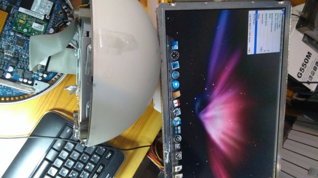
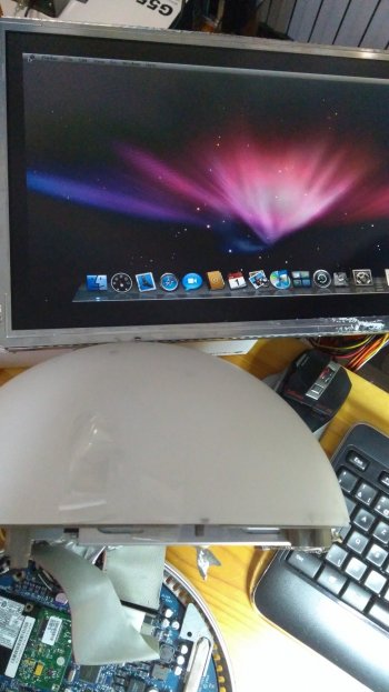
[Solved] iMac G4 1.0 15" "FP" (USB 2.0) LCD repair - 17" screen on 15" board
- Thread starter NG4KC
- Start date
- Sort by reaction score
You are using an out of date browser. It may not display this or other websites correctly.
You should upgrade or use an alternative browser.
You should upgrade or use an alternative browser.
Are you sure that this resistor is broken? Did you measure an open line? If you are looking for a 250 ohm Thin Film Resistor you could look a Mouser Electronics. But they would probably want that you buy in bulk. Probably best to look at AliExpress e.g. https://dutch.alibaba.com/product-d...offerlist.normal_offer.d_title.3efd48177TDzRt
However, this takes a month to arrive in Italy. You could also buy locally a normal 250 ohm resistor and see if it works for you. You could then later replace it with a proper one
However, this takes a month to arrive in Italy. You could also buy locally a normal 250 ohm resistor and see if it works for you. You could then later replace it with a proper one
USB3foriMac
macrumors 6502
That's a huge voltage drop across this inductor. 3.49 - 1.1 = 2.29V.it's 3.49V before L82, 1.10V after L82, measures taken with negative on another point.
If I test V on component poles it's 2.39V
To me not enough supply to lcd.
If this component overheated could it be damaged? I can't see any more options after this.
Small measurement error probably by individual measurement. The results should be same. You can measure across, provided your multimeter is handheld and not AC powered Lab meter.If I test V on component poles it's 2.39V
This either means the inductor has a huge resistance, hence faulty, or there is a huge current.
So switch off, and measure resistance across this resistor. It should be an Ohm or two.
Definitely voltage too low.Sheet n.53 of schematics, top right corner, indicates an exit V of 3, 1.10 is lower.
Unless it draws V according to needs.
What is the "blob" on the edge of L82. It looks like solder that could make a shortcut.
No, it's flux. Nothing to worry about. Normally, factory removes this. It could mean that someone did hand soldering. Also happens at factory, e.g. if components were not placed properly by the placer machine. So many years ago, the process wasn't as good as today.I think it's glue or some insulator, there's more on the IDE pins and power connector.
I'm not too sure it isn't this component giving trouble.
When you desolder components, there is normally a tiny glue spot underneath. Most times it's red. But it is much smaller, only visible on the bottom after the component is removed. So when you apply solder you need to heat up the component a bit longer and push it a bit with your tool tip. But be careful not to damage the thin PCB tracks. Then it becomes worse.
If the inductor is high ohmic and since the inductor is just for protection, you can simply solder a small wire over the top, or put a solder blob onto it. If it is already low ohmic, then there is a large current which could mean that the panel is indeed faulty. Such high voltage drop is by no means normal.
My multimeter is battery powered.
This morning I measured, AC plugged but mac powered off:
-L82, around +160 ohms both ways (powered is - 160, but that's the multimeter)
AC plug off:
-L82, varies from 80 to 150, could be some cap in between; waiting later (a hour or so) to get back home.
This morning I measured, AC plugged but mac powered off:
-L82, around +160 ohms both ways (powered is - 160, but that's the multimeter)
AC plug off:
-L82, varies from 80 to 150, could be some cap in between; waiting later (a hour or so) to get back home.
USB3foriMac
macrumors 6502
You can't measure ohm when powered. This will give you false measurements.My multimeter is battery powered.
This morning I measured, AC plugged but mac powered off:
-L82, around +160 ohms both ways (powered is - 160, but that's the multimeter)
AC plug off:
-L82, varies from 80 to 150, could be some cap in between; waiting later (a hour or so) to get back home.
When powered off, other components can affect your measurement. However, with the display unplugged, the inductor is at the end of the track (didn't look at the schematic, so I'm assuming here), and in such case the measurement will not be affected by any other component, unless there is something in parallel (it's nearly midnight here, please check by yourself).
If the inductor is indeed 160 ohms, it's far too much. Check some other inductors, see what they have. Can't be that all of them are faulty, right?
I'll do as you suggest.You can't measure ohm when powered. This will give you false measurements.
When powered off, other components can affect your measurement. However, with the display unplugged, the inductor is at the end of the track (didn't look at the schematic, so I'm assuming here), and in such case the measurement will not be affected by any other component, unless there is something in parallel (it's nearly midnight here, please check by yourself).
If the inductor is indeed 160 ohms, it's far too much. Check some other inductors, see what they have. Can't be that all of them are faulty, right?
In fact, they can't be all faulty 🙂
Thanks!
USB3foriMac
macrumors 6502
Yes, that's good. Many small black parts are 0 Ohm resistors. You can identify them with the "0" on the schematic. So it's normal you measure a low ohm value.Most lovely people good evening,
all other Lxx smds are 0.6 ohm. All of the tested, even other smds give the same reading..
So L82 is 160 ohm? Defect. Bridge it with a wire or a solder blob.
If you want to replace it with the original component, check the size! These are 0602 or 0304 etc, which means 6 X 2 mm or 3x4mm etc. Once you have the size, you can choose a medium Microhenry value. So if you get this part with 0.1 uH to 10 uH, choose 1 uH.
As mentioned, this is a protective component only as inductors avoid current peaks, but it is not used as an inductor in a resonance circuit or anything where the value matters.
The higher the uH, the higher resulting ohmic value. And you don't want the ohms of this to be too high as otherwise it burns away or the screen doesn't work.
Last edited:
I'll order some asap.Yes, that's good. Many small black parts are 0 Ohm resistors. You can identify them with the "0" on the schematic. So it's normal you measure a low ohm value.
So L82 is 160 ohm? Defect. Bridge it with a wire or a solder blob.
If you want to replace it with the original component, check the size! These are 0602 or 0304 etc, which means 6 X 2 mm or 3x4mm etc. Once you have the size, you can choose a medium Microhenry value. So if you get this part with 0.1 uH to 10 uH, choose 1 uH.
As mentioned, this is a protective component only as inductors avoid current peaks, but it is not used as an inductor in a resonance circuit or anything where the value matters.
The higher the uH, the higher resulting ohmic value. And you don't want the ohms of this to be too high as otherwise it burns away or the screen doesn't work.
Thanks for helping solve this thing. I'll try it later today.
Without the schematics I'd never thought to check that component.
There was a plastic thing close to L82 and it did melt, means to me at least 70°C.

USB3foriMac
macrumors 6502
Congratulations!!!I blobbed the thing and it works.
Another revival success!
Thanks again. I wish I had your knowledge.Congratulations!!!
Another revival success!
Not a lamp 😉 But yours are truly beautiful.Excellent, another iMac G4 saved
I'm going to write a summary in the first post and change the title of the thread to help others.
Register on MacRumors! This sidebar will go away, and you'll see fewer ads.